Honeywell TC300 Commercial Thermostat
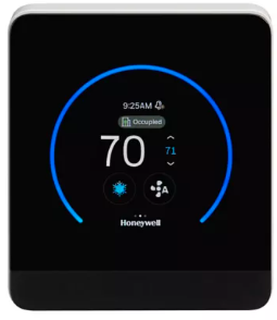
INTRODUCTION – Honeywell
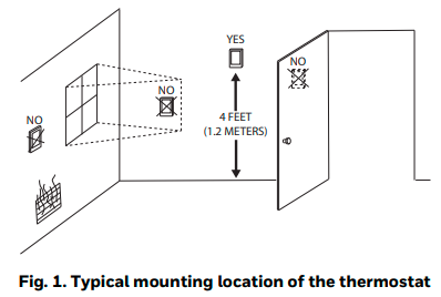
TC300 Commercial Touchscreen Thermostat is designed to be wall-mounted indoors. Mount in a clean, dry location away from windows, air ducts, and other places where environmental factors may affect temperature and humidity readings. If you mount the Thermostat on the interior of an outside wall, thoroughly insulate it so the outside air behind the sensor does not affect the sensor reading. To meet the requirements of the Americans with Disabilities Act, mount no higher than 48″ from the floor and with a minimum clear floor space of 30″ X 48″ (760 X 1220 mm).
Supported Documents
- TC300 Commercial Thermostat Datasheet (31-00645)
- TC300 Commercial Thermostat User Guide (31-00644)
- TC300 Commercial Thermostat Pocket Guide (31- 00648)
- TC300 Deco Plate Pocket guide (31-00657)
- TC300 BACnet Integration guide (31-00646)
- TC300 Safety Sheet (31-00643)
When installing this product
- Read these instructions carefully. Failure to follow them could damage the product or cause a hazardous condition.
- Check the ratings given in the instructions and marked on the product to make sure the product is suitable for your application.
- The installer must be a trained, experienced service technician.
- After installation is complete, check the product operation.
- Be sure wiring complies with all applicable codes, ordinances, and regulations.
USING EXTERNAL TEMP./HUM. SENSORS
When using the remote-mounted temperature (and humidity) sensor(s) to sense ambient conditions, install the Thermostat in an area that is accessible for setting and adjusting the temperature and settings.
Power supply guidelines and requirements
The thermostat uses 24VAC power from a UL Listed Class2 24VAC transformer (not provided in the kit). It also uses a half-wave rectifier to convert the AC power supply to onboard power. This enables multiple devices with halfwave power supplies to be powered from a single, grounded transformer.
WARNING
Half-wave devices and full-wave devices must not use the same AC transformer. You must maintain wiring polarity. Failure to do so can result in equipment damage. If the HVAC equipment has an internal circuit board that is powered by the same transformer that will power the Thermostat, verify that it is NOT full wave.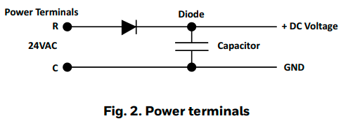
Power supply wire sizing
Long power supply wiring runs require selecting the wire gauge appropriately. If the wire gauge is inadequate the increased resistance and associated voltage drop may result in insufficient voltage supply to the Thermostat. The recommended wire gauge guidelines are as follows.
- Min. Load = 4VA (all DOs OFF, No Sylk sensor).
- If the 14-18AWG wire is used for R, C terminal, Max. Load = 4A, 96VA (all DOs ON).
- If the 20-22AWG wire is used for R, C terminal Max. Load = 3A, 72VA (all DOs ON).
- If the 24-26AWG wire is used for R, C terminal, Max. Load = 2A, 48VA (all DOs ON)
DO1, DO2, DO3, DIO1, and DIO2 all relay outputs are powered from the external transformer. The minimum load includes the Thermostat and analog outputs at full load (Max. 10V voltage output with 2Kohms load). Every relay output is N.O. (Normally Open) contacts with a maximum switch rating of 24VAC @1A (24VA). The allowed maximum load is 96VA, which assumes all 5 relay output loads are powered from the transformer. Actual power requirements depend on connected loads.
Mounting wallplate on the drywall
Mount the wallplate vertically on the wall. It supports 14- 26AWG (0.2-1.5mm2 for solid or stranded, max 2.5mm2 for solid) wires.
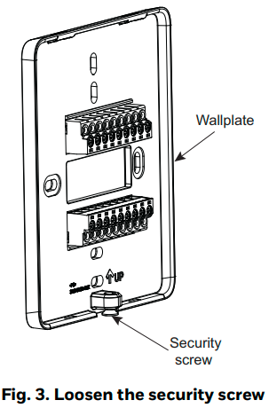
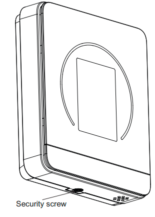
- At the bottom of the thermostat, loosen the Security screw using a screwdriver by turning it in counterclockwise direction.
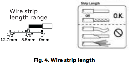
- Before mounting the wallplate, make sure that the thermostat wires are stripped to the length marked on the wallplate.
- Position and level the wallplate along the wall and mark the drilling location using a pencil.
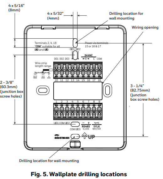
- Remove the wallplate and drill two pilot holes on the wall, on the marks. For drywall, drill 3/16” (5mm) holes. For firmer material such as plaster, drill 7/32” (6mm)holes.
- Gently tap anchors (provided in the kit) into the pilot holes until flush with the wall.
- Pull the wires through the wiring opening of the wallplate and position the wallplate over the mounting holes. See Fig. 8 Wiring.
- Insert the screws into the holes and tighten (screw torque 0.1Nm).
Mounting the wallplate on the junction box (optional)
TC300 can support vertical mounting of US 2″x4″ junction boxes, vertical and horizontal mounting of 75*75mm, 86*86, and European round(ø71 for German and ø75 for French) junction boxes.
- Install the junction box and perform the wiring as per its manufacturer’s instructions.
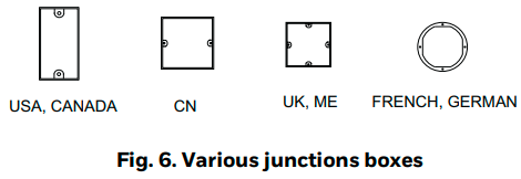
- Before mounting the wallplate, make sure that the thermostat wires are stripped to the length marked on the wallplate.
- Pull the wires through the wiring opening of the wallplate and position the wallplate along the junction box to align the mounting holes. For junction box screw holes, refer to Fig. 5.
- Insert the screws into the holes and tighten them.
Accessories ordering part numbers

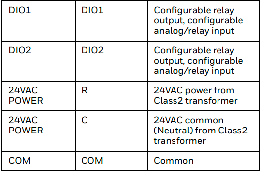
Terminal identification
WARNING
Do NOT wire the thermostat to line voltage.
Wiring the wallplate
IMPORTANT
All wiring must comply with local electrical codes and ordinances.
NOTE: Supports 14-26AWG (0.2-1.5mm2 for solid or stranded, max 2.5mm2 for solid) wires.
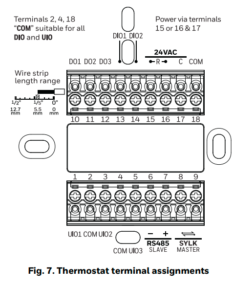
Follow equipment manufacturer wiring instructions when available. A letter code is located near each terminal for identification.
CAUTION
Power must not be connected while wiring. Wiring a unit that is powered may result in electrical shock and/or equipment damage.
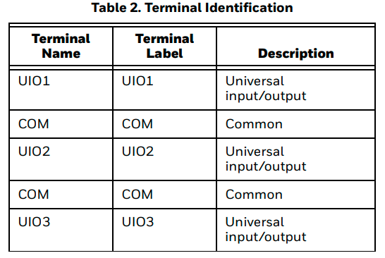
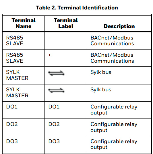
- Connect wires to the terminals. See Fig. 7 for terminal assignments and Table 2 for terminal descriptions.
- Loosen the terminal screw, and insert the solid wire (twist if it is stranded) into the wiring terminal hole directly.
- Tight the terminal screw using the Phillips screwdriver (screw torque 0.4Nm).
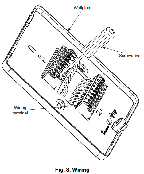
- Push excess wire back into the hole.
- Check for loose or frayed wire that may cause a short.
Mounting the display unit
After all wiring is completed, install the display onto the wallplate.
- Hold the display unit in a forward-tilted position and align the slots in the display unit with the protrusions on top of the wall plate.
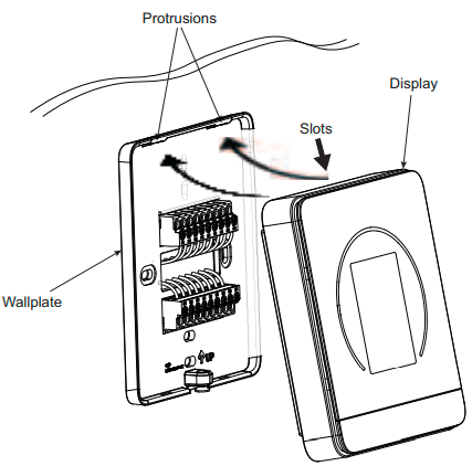
- Carefully pivot the display onto the wall plate to ensure proper engagement of pins with terminal blocks while ensuring the engagement of protrusions and slots is maintained as shown in step 1.
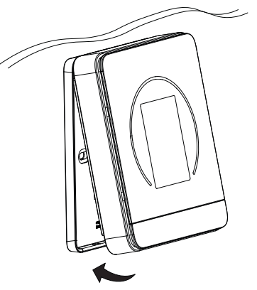
- Gently tighten the Security screw using a screwdriver by turning it in the clockwise direction (screw torque 0.1Nm).
Dismounting the display unit
- Unscrew the security screw.
- Detach the bottom side by pulling the display unit out and detach the top side.
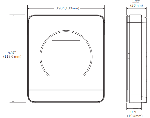
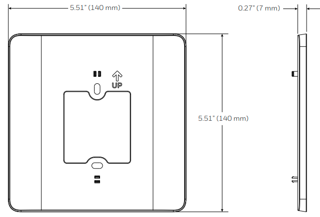
DIMENSIONS
Thermostat
Decoplate
WEEE (Waste of Electrical and Electronic Equipment)
- At the end of the product life, dispose of the packaging and product in an appropriate recycling center.
- Do not dispose of the device with the usual domestic refuse.
- Do not burn the device.
This symbol on our product shows a crossed-out “wheelie bin” as required by law regarding the Waste of Electrical and Electronic Equipment (WEEE) disposal. This indicates your responsibility to contribute to saving the environment by proper disposal of this Waste i.e. Do not dispose of this product with your other wastes. To know the right disposal mechanism please check the applicable law.
Regulation (EC) No 1907/2006
According to Article 33 of Reach Regulation be informed that the substances listed below may be contained in these products above the threshold level of 0.1% by weight of the listed article.
By using this Honeywell literature, you agree that Honeywell will have no liability for any damages arising out of your use or modification to, the literature. You will defend and indemnify Honeywell, its affiliates, and its subsidiaries, from and against any liability, cost, or damages, including attorneys’ fees, arising out of, or resulting from, any modification to the literature by you.
Honeywell Building Technologies
715 Peachtree Street NE Atlanta, GA 30308
https://customer.honeywell.com
https://buildings.honeywell.com
For More Manuals by Honeywell, Visit Latest Manuals
FAQs About Honeywell TC300 Commercial Thermostat
How can I determine a Honeywell thermostat’s age?
DATE CODE: This indicates when the thermostat was manufactured. The Date Code is a four-digit code that may be found on the rear of the detachable face plate of most thermostats. The model and serial number of your thermostat are indicated by this. The Model Number of the majority of thermostats may be found on the rear of the removable face plate.
Does the Honeywell thermostat change the temperature by itself?
Auto-changeover is a feature of the Lyric T6 Pro thermostats. This enables the thermostat to switch between heating and cooling in response to the room temperature and the set points for each function. It is not set up for auto-changeover if “auto” is not displayed as an option on your thermostat.
The Honeywell thermostat: How does it operate?
When the thermostat is turned to “on” and “cool,” the device will operate until the temperature is reached, at which point it will shut off. It is necessary to turn on and chill the thermostat to cool. It is also necessary to specify a temperature so that the device understands when to turn on and off.
Is the Honeywell thermostat supposed to be on or off?
By keeping your thermostat set to AUTO, you can significantly lower your overall energy consumption and utility costs. Furthermore, if you keep your fan running constantly, or in the “on” position, it will last longer than your air filter.
My Honeywell thermostat isn’t heating; why is that?
Verify that the thermostat is configured correctly to ensure that the equipment is being controlled. Check to make sure the thermostat is hooked properly. Verify that every wire is safely tucked into its proper termination. Depending on the thermostat model, confirm that the voltages are between 18 and 30 VAC or 20 and 30 VAC.
Can the thermostat on a Honeywell break?
Can a Thermostat malfunction? Indeed. Since your thermostat serves as your primary means of communication with your HVAC system, it must function correctly and consistently.
What does a Honeywell thermostat’s temporary mode represent?
When you adjust the temperature to a different setting, it remains there until the next schedule modification. This is known as the temporary hold setting. The temperature you have selected is stored for an infinite amount of time in the permanent hold option. This overrides the settings you have scheduled. Was there any value in this article?
Can Honeywell thermostats be switched?
Several Honeywell Home T-Series thermostats are installed on Universal Wall Plates, which enable you to switch between models by just “plugging” one in place of the other. This is an additional aid.
A Honeywell thermostat is powered by what?
The thermostat cannot power itself unless a C wire is attached to the C port on the device.
What is the ideal location for a Honeywell thermostat?
It is not recommended to position the Honeywell Home Thermostats in direct sunlight, next to heat sources, or near drafts. It ought to be at least 1.5–2 meters above the ground. Given how easily the temperature can change in the kitchen, it is not a smart idea to install a thermostat there.


