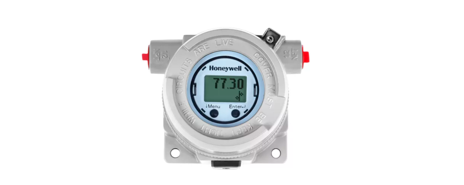
Honeywell STT700 SmartLine Temperature Transmitter
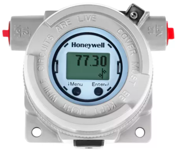
Installation – Honeywell
For start-up, operation (including configuration), maintenance, and calibration refer to the STT700 Transmitter User’s manual, #34-TT-25-17 Evaluate the site selected for the Transmitter installation concerning the process system design specifications and Honeywell’s published performance characteristics for your particular model. Conditions to be considered include: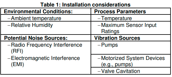
In preparation for post-installation processes, refer to the MC Toolkit User Manual, Document # #34-ST-25-50 (MCT404), for battery conditioning and device operation and maintenance information.
DEVICE CONFIGURATION
This transmitter comes with a standard factory configuration. Consult the nameplate for basic information. Reconfiguration for your particular application can be accomplished by following instructions in the Transmitter User’s manual. This can be found by following the website URL or QR code on page 1 of this document.
Features and Options
As shown in Figure 1, the STT700 is packaged in a single module. The elements in this module are connected to the process sensors, measure the process variables, respond to setup commands, and execute the software and protocol for the different temperature measurement types.
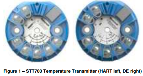
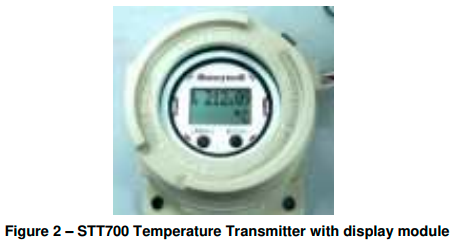
The transmitter measures process temperature and outputs a signal proportional to the measured process variable (PV). Available output communication protocols include 4 to 20mA, Honeywell Digitally Enhanced (DE), and HART protocols.
Mounting the Transmitter
DIN Rail Mounting
If the STT700 is to be installed on DIN Rail then the main considerations are electrical connections and mechanical fixing. Electrical connections are identical to the bench test instructions except that thermocouple wire is likely to be used with thermocouples. Mechanical fixing of the module is using the snap-in DIN Rail Clips which are screwed to the bottom lugs of the module.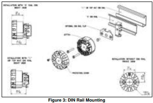
Mounting Module in Housing
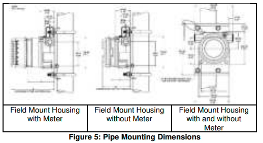
The STT700 module can be installed in a variety of housings suitable for direct head mounting, 2” (50mm) pipe mounting, or wall mounting.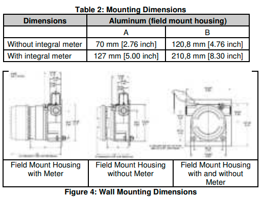
Spring Loading
Spring loading is available worldwide with direct head mounting. In North America, spring loading is typically included in the sensor/thermowell assembly and is available with all housings. For non-North American spring loading as shown in Figure 6, simply include the springs under the 33 mm pitch mounting screws, pass the screws through the module and sensor mounting plate and snap in the retaining circlip to the screws to hold the assembly together.
Guide the sensor assembly through the housing sensor entry and screw down the 33 mm screws until the limit is reached as the sensor presses against the bottom of the thermowell. For more details on wiring and dimensions for the Aluminum Direct head and Cast iron Direct head refer to the STT700 SmartLine transmitter user’s manual, #34-TT-25-17.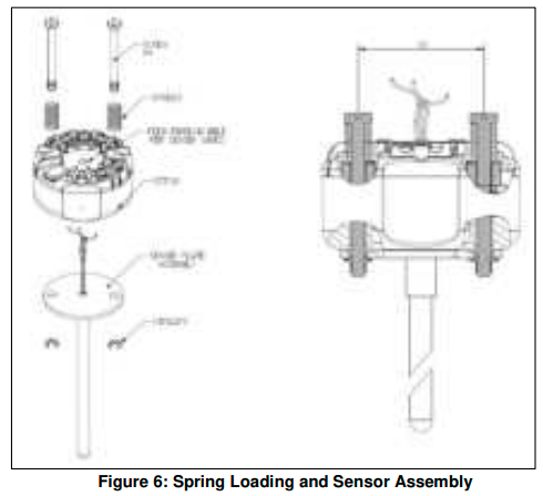
Wiring Connections and Power-Up
Summary
The transmitter is designed to operate in a two-wire power/current loop with loop resistance and power supply voltage within the HART and DE operating ranges shown in Figure 7.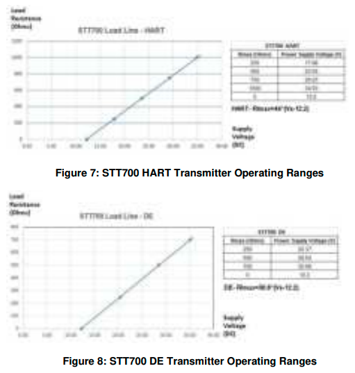
Loop wiring is connected to the transmitter by simply attaching the positive (+) and negative (–) loop wires to the positive (+) and negative (–) terminals on the transmitter terminal block in the electronics housing shown in Figure 9.
Route the wires through the pre-molded channels on the connector cap. Connect the loop power wiring shield to earth ground only at the power supply end.
Note that the loop-power for this transmitter is not polarity-sensitive.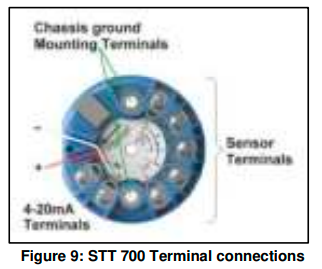
Wiring Variations
The above procedures are used to connect power to a transmitter. For loop wiring and external wiring, detailed drawings are provided for transmitter installation in non-intrinsically safe areas and intrinsically safe loops in hazardous area locations. This procedure shows the steps for connecting power to the transmitter.
Input Sensor Wiring
Connect the input sensors as shown in Figure 10 below RTD Thermocouple, mV, Ohm, and Millivolt connections.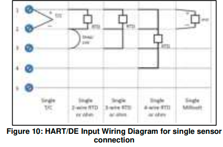
The single-sensor connections can also be used on a dual-input transmitter when a second input is not required. In this case, it is recommended that the second input be configured to none in the software. In case of RTD type being configured to 4-wire, this is automatically done.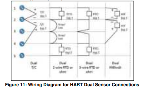
LIGHTNING PROTECTOR
This device is designed to give the SmartLine temperature transmitter maximum protection against surges such as those generated by lightning strikes. The lightning protector mounts right on the top of the STT700 terminal block, providing easy field wiring and also protection for the EU meter if used. For more details refer to the STT700 SmartLine temperature transmitter user’s manual, #34-TT-25-17.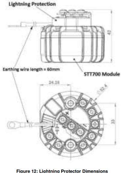
Installation
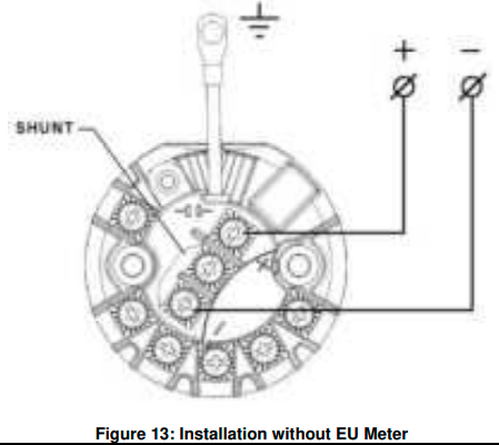
- If an EU meter is used, remove the shunt on the Lightning Protector. In all other cases, the shunt must be present.
- If Standard Display is used, no need to remove the shunt.
- Remove the cover/cap of the housing (if applicable). The device fits on the top of the transmitter module terminal block and the transmitter output screws (+ and -) fix mechanically the device.
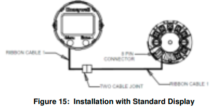
- If Standard Display is used, remove the cover of the housing and connect the display cable to the 8-pin connector provided on the transmitter.
- Attach the grounding wire to the ground screw in the housing. Connect a wire from the transmitter enclosure to local earth ground. Use size 14 AWG or 2.0mm2 bare or green covered wire.
- If an EU meter is used, wire according to Figure 14 Standard Display is used, wire according to Figure 15.
- Connect the 4 – 20mA loop to the + and – terminal screws of the surge protection and close the cap of the housing.
For a start-up, operation (including configuration), maintenance, and calibration refer to the STT700 Transmitter User’s manual, #34-TT-25-17
Appendix A. PRODUCT CERTIFICATIONS
- A1. Safety Instrumented Systems (SIS) Installations
For Safety Certified Installations, please refer to STT700 Safety Manual #34-TT-25-05 for installation procedure and system requirements. - A2. China RoHS
China RoHS compliance information is located here: (Pending)
www.honeywellprocess.com
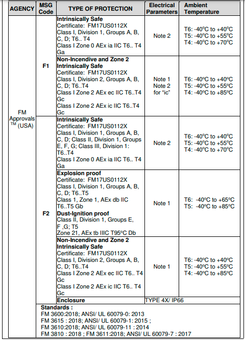
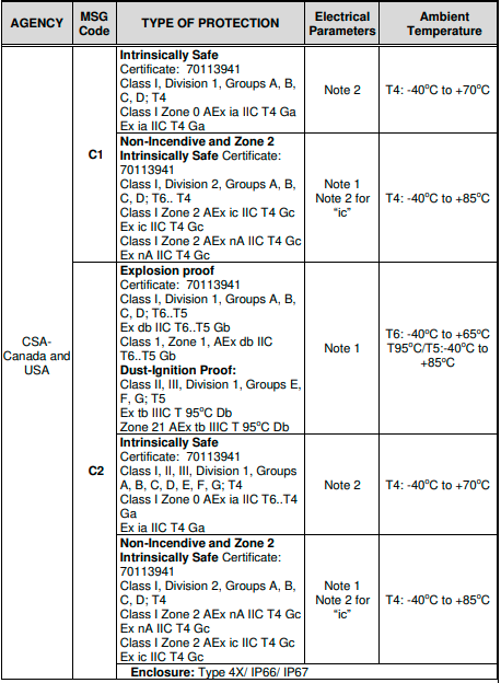
Hazardous Locations Certifications
WARRANTY
Honeywell warrants goods of its manufacture as being free of defective materials and faulty workmanship. Contact your local sales office for warranty information. If warranted goods are returned to Honeywell during the period of coverage, Honeywell will repair or replace without charge those items it finds defective.
The foregoing is Buyer’s sole remedy and is instead of all other warranties, expressed or implied, including those of merchantability and fitness for a particular purpose. Specifications may change without notice. The information we supply is believed to be accurate and reliable as of this printing. However, we assume no responsibility for its use.
While we provide application assistance personally, through our literature and the Honeywell website, it is up to the customer to determine the suitability of the product in the application.
Sales and Service
For application assistance, current specifications, pricing, or the name of the nearest Authorized Distributor, contact one of the offices below.
ASIA PACIFIC (TAC) hfs-tac-support@honeywell.com
Australia Honeywell Limited, Phone: +(61) 7-3846 1255,
Toll Free 1300-36-39-36, Toll Free Fax: 1300-36-04-70
China – PRC – Shanghai, Honeywell China Inc. Phone: (86-21) 5257-4568,
Fax: (86-21) 6237-2826
Singapore, Honeywell Pte Ltd. Phone: +(65) 6580 3278. Fax: +(65) 6445-3033
South Korea, Honeywell Korea Co Ltd. Phone (822)799 6114. Fax:+(822) 792 9015
EMEA, Phone: + 80012026455 or +44 (0)1202645583.
Email: (Sales) FP-Sales-Apps@Honeywell.com
or (TAC) hfs-tac-support@honeywell.com
Web: Knowledge Base search engine http://bit.ly/2N5Vldi
AMERICAS, Honeywell Process Solutions,
Phone: (TAC) 1-800-423-9883 or 215/641-3610. (Sales) 1-800-343-0228.
Email: (Sales) FP-Sales-Apps@Honeywell.com
or (TAC) hfs-tac-support@honeywell.com
Web: Knowledge Base search engine http://bit.ly/2N5Vldi
For more information
To learn more about SmartLine transmitters, visit the process. Honeywell
Or contact your Honeywell Account Manager
Process Solutions
Honeywell 1250 W Sam Houston Pkwy S Houston, TX 77042 Honeywell Control Systems Ltd Honeywell House, Skimped Hill Lane Bracknell, England, RG12 1EB Shanghai City Centre, 100 Jungi Road
Shanghai, China 20061
process.Honeywell
This document provides descriptions and procedures for the Quick Installation of Honeywell’s family of SmartLine Temperature Transmitters.
Copyrights, Notices and Trademarks
Copyright 2023 by Honeywell Revision 7, May 2023
Trademarks
SFC, SmartLine, and STT700 are U.S. registered trademarks of Honeywell Inc. HART® is a Trademark of FieldComm Group™
Documentation
To access complete documentation, including language variants, scan the QR code below using your smartphone/device or QR code scanner. Go to the APP store for your free Smartphone QR scanner Or you can follow the URL to access the online SmartLine HUB page. The HUB page will contain direct links to open SmartLine product documentation.
URL: SmartLineHUB
QR Code

FAQs About Honeywell STT700 SmartLine Temperature Transmitter
What is the temperature transmitter’s working principle?
Temperature transmitters typically send (transmit) a standardized output signal to the control device after isolating, amplifying, filtering noise, linearizing, and converting the input signal from the sensor. Electrical output signals in the 4-20mA or 0-10V DC range are frequently employed in industrial facilities.
How is the Honeywell temperature calculated?
The way that Honeywell digital thermostats display the room temperature is meant to mimic how humans perceive temperature. This indicates that the thermostat considers both the room’s ambient air temperature and the radiant temperature of the furniture and walls.
What frequency does the Honeywell transmitter operate at?
345 MHz is the transmitter frequency. RF range: from panel to up to 100 feet. Model: two-zone transmitter with integrated magnetic reed switches on each side.
In what sense is a temperature transmitter accurate?
The full-scale accuracy of thermocouple and RTD transmitters is ±0.1%. Additionally, temperature transmitters maintain stability by shielding signals from radiofrequency and electromagnetic interference.
Is a transmitter of temperature an input or an output?
Temperature transmitters typically send or transmit a standardized output signal to the control device after isolating, amplifying, filtering noise, linearizing, and converting the input signal from the sensor. Electrical output signals in the 4-20mA or 0-10V DC range are frequently employed in industrial facilities.
What is the calibration of a temperature transmitter?
A device that generates a range of resistances takes the place of the sensor during the temperature transmitter calibration process. For calibration, a specialized tool that mimics thermocouples and RTDs is used. Calibration devices are USB-connected to computers and are programmed using specialized software.
Where is the thermostat sensor for a Honeywell located?
A thermostat’s temperature sensor is usually found inside the device itself.
Why is the heat not functioning on my Honeywell?
Make sure the thermostat is first set to the Heat setting. Ensure that the temperature is higher than the reading on the inside. Additionally, examine the circuit breaker and reset it if required. Verify that the furnace door is shut firmly.
What powers a Honeywell thermostat?
The thermostat is “supplied” to the R/RC terminals and “returns” through the C terminal, operating between 20 and 30 VAC. For the thermostat to run on its energy, a C wire that is linked to C on the apparatus is needed. Make sure the breakers, power switch, and furnace/air handler door are all turned on.
How can I check the functionality of my Honeywell thermostat?
The thermostat should react practically instantly when you change the temperature setting. Most likely, you’ll hear a faint clicking sound and then the sound of air passing through the ducting. To check if the air is hot or cold, you can also put your palm over a vent.
For More Manuals by Honeywell, Visit Latest Manuals
 |
Honeywell STT700 SmartLine Temperature Transmitter Installation Guide [pdf] |

