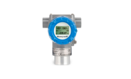
Honeywell SmartLine STT650 Temperature Transmitter

SAFETY INSTRUCTIONS
Receipt and unpacking
Unpack the device without damaging it. The packing should always follow the device until this has been permanently mounted. Check at the receipt of the device whether the type corresponds to the one ordered.
Environment
Avoid direct sunlight, dust, high temperatures, mechanical vibrations, and shock, as well as rain and heavy moisture. If necessary, heating more than the stated limits for ambient temperatures should be avoided by way of ventilation.
Mounting
Only qualified technicians who are familiar with the technical terms, warnings, and instructions in this installation guide and who can follow these should connect the device. Should there be any doubt as to the correct handling of the device, please contact your local distributor or Honeywell.
Calibration and adjustment
During calibration and adjustment, the measuring and connection of external voltages must be carried out according to the specifications of this installation guide. The technician must use tools and instruments that are safe to use.
Cleaning
When disconnected, the device may be cleaned with a cloth moistened with distilled water.
The installation guide for technical personnel covers the following products: STT 650 UNI PROG, STT 650 RTD PROG, STT 650 HART, STT 650 FF, and STT 650 Plus.
Input signals

- RTD
- TC
- Voltage
- Lin R – Ω
- Difference, redundancy* or average; RTD, TC or mV
output signals

- Current
- HART
- PROFIBUS
- FOUNDATION FIELDBUS
Max. wire size 1 x 0,13 .. 2,08 mm2 stranded wire. Screw terminal torque 0.5 Nm.
PC programming of SmartLine Temperature STT 650
The device is configured to the present task by way of a PC and Honeywell communications interface STT17C. Redundancy is applicable only for FF/Profibus models. The device can be configured with or without a connected supply voltage as the communications interface supplies the necessary voltage to the set-up. The communications interface is galvanically isolated to protect the PC port.
Electrical specifications
- Specifications range ………….. -40°C to +85°C Supply voltage,
- STT 650 UNI PROG …………… 7,2 .. 35 VDC Supply Voltage STT 650 UNI PROG
- (Intrinsically Safe) ……………….. 7.2 … 30 VDC Supply voltage, STT 650 RTD PROG & STT
- 650 HART ………………………… 8,0 … 35 VDC Supply Voltage STT 650 RTD PROG & STT
- 650 HART (Intrinsically Safe) … 8.0 .. 30 VDC Supply voltage,
- STT 650 FF/Pbus………………….. 9.0…32 VDC Supply Voltage
Current output: - Signal range ……………………………. 4…20 mA
- Min. signal range …………………..….. 16 mA
- Load resistance, ∧ ≤ (Vsupply-7.2V)/0.023
Mounting on DIN rail

Demounting from DIN rail

First, remember to demount the connectors with hazardous voltages. Detach the device from the DIN rail by lifting the bottom lock.
STT170C is a communications interface that is needed for configuring STT 650 Programmable and HART units. STT 650 is not approved for communication with devices installed in hazardous (Ex) areas.


China RoHS

This table is prepared by the provisions of SJ/T 11364
- O: Indicates that said hazardous substance contained in all of the homogeneous materials for this part is below the limit requirement of GB/T 26572.
- X: Indicates that said hazardous substance contained in at least one of the homogeneous materials used for this part is above the limit requirement of GB/T 26572.
Tel: 1-800-423-9883 [Technical Support] or 1-800-343-0228 [Presale]
www.process.honeywell.com
Documentation, permits, and other information can be found on the internet at https://www.process.honeywell.com/smartline-stt650.aspx
For More Manuals by Honeywell, Visit Latest Manuals
FAQs About Honeywell SmartLine STT650 Temperature Transmitter
Is there a temperature transmitter in the Honeywell STT650?
The STT650 is a DIN Rail mounted high-performance temperature transmitter that is a member of the SmartLine® product family. It provides high measurement accuracy, stability, and dependability over a wide range of processes and ambient temperatures.
What is the temperature transmitter’s working principle?
The working concept of a temperature transmitter
The signal from a temperature sensor (such as a thermocouple or resistance temperature sensor PT100) is amplified by temperature transmitters, who also make sure the signal is linearized and converted into a voltage signal (0–10 V) or a current signal (0–20mA, 4–20mA).
What does a temperature transmitter unit mean?
A temperature transmitter is the best option for many distant temperature measurement applications since it transforms an RTD or thermocouple signal into a 4–20 mA output signal.
How long does a temperature transmitter last?
Thermocouples, as previously mentioned, are more resilient and can withstand high temperatures and vibrations. Thermistors and RTDs have higher sensitivity. Under ideal circumstances, the lifespan of each type of sensor can range from 20 to 25 years.
What does the temperature transmitter’s SI unit mean?
The limits of thermometers vary. Kelvin (K) is the S.I. unit of temperature; 1K is equal to -273.15 degrees Celsius.
In what sense is a temperature transmitter accurate?
ABB Temperature Transmitters Included in this series is the TTH200 head-mount temperature transmitter, which has a 0.1% accuracy and a universal sensor input for RTD probes and thermocouples.
Temperature transmitters are used where?
Transmitters’ Analogue Output for Temperature Because 10 V output signals are simple to integrate with evaluation equipment, they are widely used in power engineering, HVAC, refrigeration, and ventilation. A range of temperature transmitters using voltage signals as an output is available from WIKA.
What makes temperature transmitter calibration crucial?
Any discrepancy can be found and the sensor can be adjusted to get accurate results with the use of calibration. This is particularly crucial in sectors like food processing, pharmaceuticals, and medical equipment where temperature control is essential.
What kind of sensor measures temperature?
The most often used kind of temperature sensor is the thermocouple. They are employed in consumer, automotive, and industrial settings. Thermocouples can function over a broad temperature range, are self-powered, don’t need to be excited and react quickly.
A temperature sensor: is it digital or analogue?
analogue senses The most popular kinds of analogue sensors are light, pressure, temperature, sound, and light sensors, as was previously noted. Remember that digital versions of pressure and temperature sensors are also possible.
How can one determine whether a temperature sensor is operational?
Set your multimeter to measure resistance before attaching one probe to the outer sensor connector and the other to the sensor across from it to test a temperature sensor. After a few seconds, note the values, which should be between 250 and 1000 ohms, respectively, after submerging in hot and then icy water.
What are a temperature transmitter’s input and output?
What does a temperature transmitter’s output mean? Since temperature transmitters serve as both the sensor’s and the receiver’s medium, they ought to produce a value that the receiver’s apparatus can measure. The standard output of a temperature transmitter in the industry is either 0-5VDC, 0-10VDC, or 4-20mA.
What is the calibration of a temperature transmitter?
A device that generates a range of resistances takes the place of the sensor during the temperature transmitter calibration process. For calibration, a specialised tool that mimics thermocouples and RTDs is used. Calibration devices are USB-connected to computers and are programmed using specialised software.
What is the number of different types of temperature transmitters?
Head mount transmitters, DIN rail or panel mount transmitters, and weather- and explosion-proof transmitters are the three main types of temperature transmitters.
What do the temperature transmitter’s zero and span adjustments mean?
The “zero” adjustment moves the instrument’s function vertically on the graph (), while the “span” adjustment modifies the function’s slope on the graph (). These two adjustments precisely match the terms of the linear function, respective