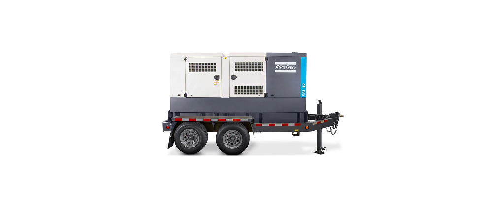
Atlas Copco QAS 150 JD Mobile Generator
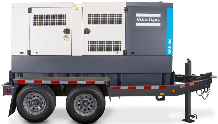
Standard Scope of Supply
- The Atlas Copco QAS 150 & QAS 200 JD T4F generators are prime power, multi-voltage, sound attenuated, mobile generators. A John Deere T4 Final liquid-cooled, six-cylinder diesel engine powers them.
- The units consist of an alternator, diesel engine, cooling system, electrical distribution, and control systems – all enclosed within a sound attenuated enclosure fabricated powder-coated zinc-rich primer 6000-hour salt spray tested.
- A broad range of undercarriage formats and options are available.
- Special attention has been given to the overall product quality, user-friendliness, ease of serviceability, and economical operation to ensure best-in-class total cost of ownership.
Available Models
- QAS 150 JD Multiple voltages – 150 kVA prime power – JD engine
- QAS 200 JD Multiple voltages – 200 kVA prime power – JD engine
Standard Features
- Compact, sound attenuated, corrosion resistant, with single point lifting and 110% fluid containment
- Dual axle trailer as standard, available as a skid-mounted unit with forklift pockets as an option
- Heavy Duty alternator with AREP excitation and marine grade protection
- Single-side service with long-run filters and 500-hour service intervals
- John Deere 6068HFG05 with Variable Speed Fan and ETM system
- Battery Charger (24V, 12A)
- External Fuel Tank connections (3-way valve) located inside the enclosure
- Identical enclosures and maintenance points between models
- Emergency Stop
- Remote signal Start / Stop
Benefits
- Extremely durable and environmentally sensitive, designed to be used for everything from the oil field to special event power
- Versatility, giving you the flexibility to match your machine to the correct application
- Start-up power for the most demanding sites with 300%overload starting capabilities
- Heavy-duty oil, air, and fuel filters extend the maintenance interval to 500 hours for a reduced total cost of ownership
- Proven engine platform with high reliability and durability, along with VSF and Exhaust Temperature Management system that minimizes the risks of wet stacking
- Onboard charger to ensure the battery is always ready for service
- Flexibility to work with an external and larger fuel tank for extended autonomy.
- Reduces stock of service kits and inventory of parts with rental ROI kept in mind
- External, recessed emergency stop for increased safety
- Allows connection as a critical backup unit via a 2-wire dry contact connection in the distribution panel.
Technical Data
| Generator | Units | QAS 150 JD | QAS 200 JD | ||
| Frequency | Hz | 50 | 60 | 50 | 60 |
| Rated Prime Power @ 400V/50Hz & 480V/60Hz 3Ø | kW / kVA | 100/125 | 120/150 | 131/164 | 160/200 |
| Rated Standby Power @ 400V/50Hz & 480V/60Hz 3Ø | kW / kVA | 110/138 | 132/165 | 144/180 | 176/220 |
| 3Ø Power Factor | 0.8 | 0.8 | 0.8 | 0.8 | |
| 3Ø Voltage @ 480V 60Hz (Series Star w/Neutral) | V | – | 480Y/277 | – | 480Y/277 |
| Amp Capacity @ 480V 60Hz | A | – | 180 | – | 241 |
| 3Ø Voltage @ 240-208V 60Hz (Parallel Star w/ Neutral) | V | – | 240Y/139 – 208Y/120 | – | 240Y/139 – 208Y/120 |
| Rated Prime Power @ 240V 3Ø | kW / kVA | – | 120/150 | – | 160/200 |
| Amp Capacity @ 240V 3Ø | A | – | 361 | – | 481 |
| Rated Prime Power @ 208V 3Ø | kW / kVA | – | 108/135 | – | 142/177 |
| Amp Capacity @ 208V 3Ø | A | – | 375 | – | 492 |
| Rated Prime Power 1Ø | kW / kVA | – | 76 / 76 | – | 102 / 102 |
| 1Ø Power Factor | – | 1.0 | – | 1.0 | |
| 1Ø Voltage @ 120-240V 60Hz (Zig-Zag) | V | – | 240/120 | – | 240/120 |
| Amp Capacity @ 240V | A | – | 316 | – | 425 |
| Amp Capacity @ 120V | A | – | 2 x 316 | – | 2 x 425 |
| 3Ø Voltage @ 400V 50Hz (Series Star w/Neutral) | V | 400Y/231 | – | 400Y/231 | – |
| Amp Capacity @ 400V 50Hz | A | 180 | – | 237 | – |
| Performance Class (acc. ISO 8528-5:1993) | G2 | G2 | G2 | G2 | |
| Single Step Load Acceptance (0-PRP) @60Hz | kW (%) | 75 (75%) | 96 (80%) | 89 (68%) | 113 (70.6%) |
| Sound Pressure Level @ 23’(7 m) @ 75% Load2 | dB(A) | 68 | 70 | 69 | 71 |
| Alternator (4 Pole, 12 Wire) | Leroy Somer | LSA 44.3 M6 | LSA 44.3 VL13 | ||
| Excitation system | AREP (auxiliary winding) | AREP (auxiliary winding) | |||
| AVR – Automatic Voltage Regulator model | D350 (std) / DVC 550 (parallel option) | D350 (std) / DVC 550 (parallel option) | |||
| AVR’s AC voltage regulation accuracy | % | ±0.25% (D350 & DVC 550) | ±0.25% (D350 & DVC 550) | ||
| Insulation | Class H | Class H | |||
| Main Breaker – Rated Current In | A | 400 | 600 | ||
| Power Distribution – Terminal Board | 5 Wire (L1, L2, L3, N, Ground) | 5 Wire (L1, L2, L3, N, Ground) | |||
| Terminal Board Connections | Bare Wire Terminals | Bare Wire Terminals | |||
| Maximum Terminal Cable Size | 350MCM | 350MCM | |||
| Convenience Receptacles3 | N/A | (2) NEMA 5-20R GFCI & (3) 125/250V 50A CS6369 | N/A | (2) NEMA 5-20R GFCI & (3) 125/250V 50A CS6369 | |
| Engine | Units | QAS 150 JD | QAS 200 JD | ||
| Model | John Deere | 6068HFG05 | 6068HFG05 | ||
| US EPA Family | MJDXL06.8312 | MJDXL06.8312 | |||
| US EPA Tier | Tier 4 Final | Tier 4 Final | |||
| Displacement | L | 6.8 | 6.8 | ||
| Cylinders | # | 6 | 6 | ||
| Continuous Engine Power Output | HP (kW) | 196 (146) | 235 (175) | ||
| Gross Engine Power Output | HP (kW) | 215 (160) | 257 (192) | ||
| Rated Speed | RPM | 1800 | 1800 | ||
| Engine Control | ECU | ECU | |||
| Aspiration | Turbocharged w/ Intercooler | Turbocharged w/ Intercooler | |||
| Engine oil capacity4 | US Gal (L) | 8.6 (32.5) | 8.6 (32.5) | ||
| Engine coolant capacity | US Gal (L) | 10.5 (39.7) | 10.5 (39.7) | ||
| Maximum Ambient Temperature (@ Sea Level)5 | °F (°C) | 120 (49) | 122 (50) | ||
| Min. Starting Temp (w/o heater) | °F (°C) | 14 (-10) | 14 (-10) | ||
| Minimum Starting Temperature (with heater)6 | °F (°C) | -13 (-25) | -13 (-25) | ||
| Electrical System (Negative Ground) | V | 24 | 24 | ||
| Engine Alternator Output | A | 60 | 60 | ||
| Battery Capacity (Cold Cranking Amps) | A | (2) 685 | (2) 685 | ||
| Fuel & DEF Systems | Units | QAS 150 JD | QAS 200 JD | ||
| Fuel Consumption @ 25% load 50Hz / 60Hz | US Gal/hr (L/hr) | 2.7 (10.2) | 3.8 (14.4) | 3.2 (12.0) | 4.1 (15.4) |
| Fuel Consumption @ 50% load 50Hz / 60Hz | US Gal/hr (L/hr) | 4.1 (15.5) | 5.2 (19.7) | 5.2 (19.7) | 6.4 (24.2) |
| Fuel Consumption @ 75% load 50Hz / 60Hz | US Gal/hr (L/hr) | 5.8 (21.9) | 6.9 (26.1) | 7.0 (26.5) | 8.2 (31.0) |
| Fuel Consumption @ 100% load 50Hz / 60Hz | US Gal/hr (L/hr) | 7.1 (26.9) | 8.2 (31.0) | 8.8 (33.3) | 10.8 (41.0) |
| Fuel Type | Ultra-Low Sulfur Diesel ONLY7 | Ultra-Low Sulfur Diesel ONLY7 | |||
| Fuel Tank Capacity | US Gal (L) | 335 (1268) | 335 (1268) | ||
| Fuel Autonomy @ 75% load and 90% of fuel capacity | Hr | 52 | 43.7 | 43.1 | 36.6 |
| DEF Tank Capacity | US Gal (L) | 25 (94.6) | 25 (94.6) | ||
| DEF Autonomy @ 75% load and 95% of DEF capacity | Hr | 139.4 | 90.0 | ||
- All ratings are at a reference condition of 0’ altitude and 20°C (72°F)
- Measured by ISO 2151 under free field conditions @ 7m distance
- Please see the receptacle voltage configuration in the Power Distribution section on page #5
- Engine oil to meet CJ-4 (low ash oil)
- Please see “Derate Table” for altitude and temperature calculations on page #4
- Coolant Heater (120V 1000W) is a standard feature.
- Engine and emissions require the use of Ultra Low Sulfur Diesel per ASTM-D975 Grade No.1-D S15 & No.2-D S15
Dimensions
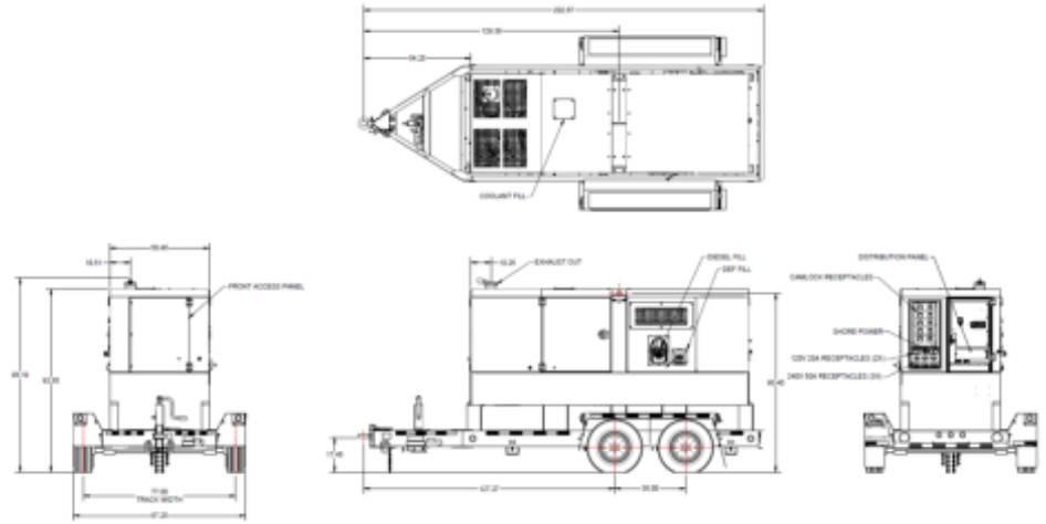
Trailer Mounted
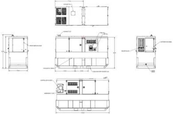
Skid Mounted
| Weight | Units | QAS 150 JD | QAS 200 JD |
| Trailer Mounted – Wet (ready to operate) | lbs (Kg) | 10,787 (4,893) | 11,062 (5,018) |
| Trailer Mounted – Dry | lbs (Kg) | 7,945 (3,604) | 8,305 (3,767) |
| Skid Mounted – Wet (ready to operate) | lbs (Kg) | 9,812 (4,451) | 10,032 (4,550) |
| Skid Mounted – Dry | lbs (Kg) | 6,970 (3,162) | 7,275 (3,300) |
| Dimensions | |||
| Trailer Mounted (L x W x H) | Inches | 203 x 87 x 98 | |
| Skid Mounted (L x W x H) | Inches | 145 x 51 x 92 | |
Principle Data
Alternator
The Leroy Somer LSA alternators are designed for heavy-duty continuous applications, with marine winding protection and Leroy Somer’s AREP excitation system.
- AREP Excitation for superior motor starting capabilities
- Marine grade (relative humidity >95%) protection
- External multi-voltage selector switch (4-position)
- 4 pole brushless design with single bearing, Class H insulation, and IP23 rating
- Voltage regulation +/- 0.25%
- Full Load acceptance of prime power rating
The AREP system uses 2 independent auxiliary windings located in the main stator to send supply voltage to the AVR:
- The voltage delivered by the first auxiliary winding H1 is proportional to the alternator output voltage (shunt characteristic).
- The voltage delivered by the second auxiliary winding H3 is proportional to the current drawn by the alternator and is a function of the applied load (compound characteristic – booster effect).
- The resulting phase-to-phase voltage supplies power to the AVR.
This power supply to the AVR power circuit is independent of the voltage sensing measured on the alternator output terminals. Therefore, the excitation current delivered by the AVR to the alternator exciter is independent of any voltage distortions (harmonics) due to the load.
The AREP system gives the alternator a high overload capacity (load impact or starting electric motors) and a short-circuit capability (300% – 10 s) to provide discriminating protection: the alternator with AREP excitation is shorter than the one with PMG excitation. It is particularly suitable for demanding applications.

Performance @ Altitude and High Ambient Conditions
When used at altitude and high ambient conditions the engine and alternator will de-rate as per the chart below.
| QAS 150 | Temperature °C (°F) | ||||||||||
| Height m (Feet) | 0 (32) | 5 (41) | 10 (50) | 15 (59) | 20 (68) | 25 (77) | 30 (86) | 35 (95) | 40 (104) | 45 (113) | 50 (122) |
| 0 | 100% | 100% | 100% | 100% | 100% | 100% | 100% | 100% | 100% | 100% | 95% |
| 500 (1640) | 100% | 100% | 100% | 100% | 100% | 100% | 100% | 100% | 100% | 100% | 95% |
| 1000 (3280) | 100% | 100% | 100% | 100% | 100% | 100% | 100% | 100% | 100% | 100% | 95% |
| 1500 (4921) | 100% | 100% | 100% | 100% | 100% | 100% | 100% | 100% | 100% | 95% | 95% |
| 2000 (6561) | 100% | 100% | 100% | 100% | 100% | 100% | 100% | 100% | 100% | 95% | 90% |
| 2500 (8202) | 100% | 100% | 100% | 100% | 100% | 100% | 90% | 90% | 90% | 85% | 80% |
| 3000 (9842) | 100% | 100% | 100% | 100% | 100% | 100% | 90% | 90% | 90% | 85% | 80% |
| 3500 (11,482) | 95% | 95% | 95% | 95% | 95% | 95% | 80% | 80% | 80% | 80% | 75% |
| 4000 (13,123) | 95% | 95% | 95% | 95% | 95% | 95% | 80% | 80% | 80% | 80% | 75% |
| 4500 (14,764) | 90% | 90% | 90% | 90% | 90% | 90% | 75% | 75% | 75% | 70% | 65% |
| 5000 (16,404) | 80% | 80% | 80% | 80% | 80% | 80% | 75% | 75% | 75% | 70% | 65% |
| QAS 200 | Temperature °C (°F) | ||||||||||
| Height m (Feet) | 0 (32) | 5 (41) | 10 (50) | 15 (59) | 20 (68) | 25 (77) | 30 (86) | 35 (95) | 40 (104) | 45 (113) | 50 (122) |
| 0 | 100% | 100% | 100% | 100% | 100% | 100% | 100% | 100% | 100% | 100% | 100% |
| 500 (1640) | 100% | 100% | 100% | 100% | 100% | 100% | 100% | 100% | 100% | 100% | 100% |
| 1000 (3280) | 100% | 100% | 100% | 100% | 100% | 100% | 100% | 100% | 100% | 100% | 100% |
| 1500 (4921) | 100% | 100% | 100% | 100% | 100% | 100% | 100% | 100% | 100% | 100% | 100% |
| 2000 (6561) | 100% | 100% | 100% | 100% | 100% | 100% | 100% | 100% | 100% | 100% | 95% |
| 2500 (8202) | 100% | 100% | 100% | 100% | 100% | 100% | 95% | 95% | 95% | 90% | 85% |
| 3000 (9842) | 100% | 100% | 100% | 100% | 100% | 100% | 95% | 95% | 95% | 90% | 85% |
| 3500 (11,482) | 95% | 95% | 95% | 95% | 95% | 95% | 85% | 85% | 85% | 85% | 80% |
| 4000 (13,123) | 85% | 85% | 85% | 85% | 85% | 85% | 85% | 85% | 85% | 85% | 80% |
| 4500 (14,764) | 75% | 75% | 75% | 75% | 75% | 75% | 75% | 75% | 75% | 75% | 70% |
| 5000 (16,404) | 70% | 70% | 70% | 70% | 70% | 70% | 70% | 70% | 70% | 70% | 70% |
Power Distribution
The main power is connected from the alternator through a 4-position voltage selector switch to the main power cubicle. The cubicle incorporates all power distribution, controls, sensing, and protection devices.
- 4-position Voltage Selector Switch (VSS)
- Current transformer x 3 (1 each leg)
- Single main breaker w/shunt trip
- Individual breakers for each receptacle
- Convenience receptacles located outside of the unit for easy access
- Terminal board for hard wiring
- Cam-Lock external quick connect (available as an option)
- External emergency stop switch (recessed)
- Neutral bonded to Ground with a removable bonding link accessible in the control cubicle
Please refer to the chart below for power distribution and voltages.
NOTE: All voltages below are subject to change, depending on the set point of the “Fine Voltage Adjustment” potentiometer and Voltage Selector Switch.
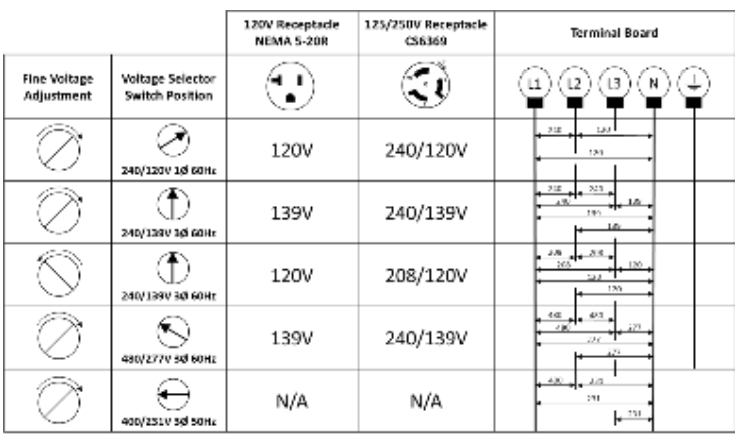
All voltages are adjustable with the “Fine Voltage Adjustment” potentiometer on the control panel. Therefore, the voltage may be different than what is shown in the above table. All voltages should be verified before connection to the unit.
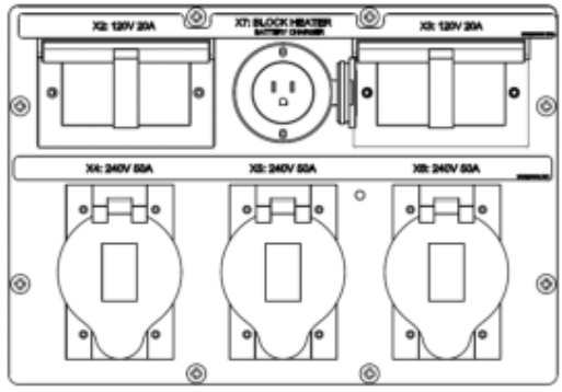
Convenience Receptacles
| Receptacle | Type |
| X2, X3 | 120V – NEMA 5-20R GFCI (outlets) |
| X4, X5, X6 | 125/250V – CS6369 (outlets) |
| X7 | 120V – NEMA 5-15P (shore power inlet for coolant heater and battery charger) |
Controller – Standard
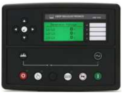
- The QAS 150 and QAS 200 JD T4F come equipped with a DeepSea 7310 control module.
- This is a fully diagnostic ECU controller with a large 3” display, that is intuitive and easy to operate with all functions conveniently at your fingertips.
- The controller also manages the engine ECU operating system, and several safety warnings and shutdowns on various parameters (listed below).
- The controller is powered by a main on/off switch located next to the unit.
DeepSea 7310 Controller Functionality:
- Home Page (displayed while running, scrolling every 3 seconds)
- Generator voltage (ph-ph)
- Status Page
- Generator voltage (ph-N)
- Generator voltage (ph-ph)
- Generator frequency
- Generator kw
- Generator power factor
- Generator amperage
- Generator Page
- Generator current (A)
- Generator earth current
- Generator load (kW)
- Generator load (kVA)
- Generator power factor
- Generator load (kVAr)
- Generator load (kWh, kVAh, kVArh)
- Generator phase sequence
- Dual mutual status
- Event Page
- Displays the last 15 events
- Remote Start/Stop
- Automatic start/stop via 2-wire dry contact connection
- Operational Buttons
- Start button
- Stop button
- Automatic mode (external remote start)
- Up/Down arrows
- Info Page
- Model number
- USB identification number
- Configured engine type
- Module date and time
- Scheduler setting
- Engine Page
- Engine speed
- Oil pressure
- Coolant temperature
- Engine battery volts
- Run Time
- Oil Temperature
- Fuel Temperature
- Turbo Pressure
- Fuel Pressure
- Fuel Consumption
- Fuel Used
- Fuel Level
- Auxiliary Sensors
- Engine Maintenance Due
- Engine ECU Link
- Engine DTC Page
- This page contains any active Diagnostic Trouble Codes that the engine ECU is currently generating. These alarms are conditions detected by the engine ECU and displayed on the DSE controller.
Controller – Paralleling Option
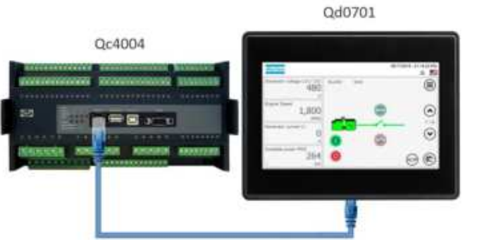
The QAS 150 and QAS 200 JD T4F are also available as an option with a Qc4004 controller and Qd0701 capacitive touchscreen display. This is a fully diagnostic ECU controller with a large 7” diagonal (800 x 480 pixel) touchscreen display that is intuitive and easy to operate with all functions conveniently at your fingertips.
The controller also manages the engine ECU operating system and several safety warnings and shutdowns on various parameters. Additionally, our Power Management System (PMS) enables the optimization of fuel consumption and expands the generator lifetime. PMS manages the number of generators running in parallel with load demand, starting and stopping units in line with increases or decreases in load.
This ensures the demand for each generator remains at a level that optimizes fuel consumption. This also eliminates the need for generators to run with low load levels, which can cause engine damage and shorten the life expectancy of the equipment.
Qc4004 Controller Benefits:
Modular Plant Capacity
- The Qc4004 controller allows up to 32 generators to be coupled in parallel to fit the power requirement of any application.
Remote communication capability
- The Qc4004 supports serial communication protocols including Modbus (RS-485, USB, and TCP/IP) and Profibus allowing you to supervise and control your genset/plant remotely.
User-friendly rental interface
- Rental companies will benefit from the standardized user interfaces. The controller has been designed with ease of operation in mind, and rental companies can easily set and lock parameters to ensure full protection of their equipment.
Available Modes:
- Island mode – Power plant with synchronizing generators or a stand-alone generator. Also applicable in critical power plants.
- Automatic Mains Failure – Critical power/emergency standby plants, black start generator.
- Fixed power – Power plant with fixed kW set point (including building load).
- Peak shaving – Power plant where generator supplies peak load demand paralleled to the mains.
- Load takeover – Plant mode where the load is moved from mains to the generator, for example, peak demand periods or periods with the risk of power outages.
- Mains power export – Power plant with fixed kW set point (excluding building load).
- Remote maintenance – Used when the generator must supply the load while a distribution transformer is disconnected for service. All modes are configurable, and it is possible to change the plant mode on the fly both in single and in power management applications.
Engine John Deere
- JD Tier 4 Final, turbo-charged, intercooler, six-cylinder, liquid-cooled diesel engine provides ample power to operate the generator continuously at full load.
- Meets all US EPA, CARB, and Environment Canada exhaust legislations with Tier 4 Final compliance.
- The engine utilizes a Selective Catalytic Reduction (SCR) and Diesel Exhaust Fluid (DEF) to meet final Tier 4 emissions. All functionality of the engine is controlled automatically on the controller.
- The engine can start the generator at 14°F (-10°C) with a standard glow-plug aid. A 1000W, 120V coolant heater is standard and allows the machine to start down to -13°F (-25°C).
- The 335 Gal (1268L) fuel tank is sufficiently sized to operate the unit at full-load condition for long run times (see the Technical Data table for specifications).
- The engine operates on a 24V negative ground electrical system with a charging alternator and lockable battery cutoff switch.
- The cooling system is suitably designed for continuous operation in ambient conditions up to 120°F (49°C), with the canopy door closed.
The cooling system is suitably designed for continuous operation in ambient conditions up to 120°F (49°C), with the canopy door closed.
Fuel System
A large 335 US Gal (1268L) PE fuel tank provides safe diesel storage while eliminating tank corrosion contaminants from being introduced to your fuel system. With an integrated fuel water separator and filter, the system is designed to help maintain a clean and trouble-free diesel supply to the engine for reliable trouble-free operation.
- Pad-lockable diesel fill cap
- Fuel / Water separator
- Inline priming pump (w/ filter)
- Fuel pre-filter
- Fuel supply pump (w/strainer)
- Fuel level sensor
- Low fuel shutdown feature (programmable level)
- External fuel connections w/3-way valve and quick disconnects
Scheduled maintenance
Standard equipped with filters sized and designed to allow 500-hour service intervals under normal operating conditions. Extended time between services reduces downtime and the total cost of ownership of the unit over its lifetime.
- 500 Hour Service Interval:
- Oil filter
- Fuel filter
- Fuel/water separator
- 1000 Hour Service Interval:
- Air filter
- Oil filter
- Fuel filter
- Fuel/water separator
NOTE: Site-specific operating conditions such as; poor fuel quality and low load profile may require more frequent service intervals.
Enclosure & Frame
The generator enclosure is designed for extreme applications to provide superior performance and reliability. The enclosure is made of carbon steel, which is zinc-rich primed, powder coated for corrosion resistance, and salt spray tested for 6000 hours.
The enclosure and frame are fully sealed from the radiator to the back of the unit, providing a true 110% containment of all fluids.
- 16Ga carbon steel, zinc-rich primed, powder-coated enclosure, 6000-hour salt spray tested
- Heavy duty, 3/16” thick steel base frame
- 110% fluid containment
- Superior level of rain ingress protection and design features
- Pad-lockable doors and fuel cap
- Engine fluid plumbed to the exterior of the frame for ease of service
- Central lifting point
- Sound dampening material and design to allow quiet operation at 68 to 71 dB(A)
Undercarriage
The QAS 150 and QAS 200 JD T4F are available with two undercarriage alternatives, providing the utmost flexibility in installation, site handling, or towing.
Both the skid frame and the trailer mount the same way and can be interchanged for versatility.
- Trailer mounted:
- Dual axle trailer
- Available with electric brakes
- DOT/Federal MVSS 49CFR571 approved light package
- Adjustable height pintle hitch (3” lunette)
- 15” Rims w/ ST225/75R15 Tires for trailer use
- Heavy Duty torsion axle
- 3/8” Safety chains with clevis slip hook and safety latch
- Screw jack leveling, with pad foot, 3,000 lbs static capacity
- Single-point lifting structure
- D-Ring Tie down points x4
- Skid mounted:
- Sub-frame skid with integrated forklift pockets
- Heavy-duty design for use in extreme conditions
- The frame is ¼” wider than a machine to reduce damage from forklifts
- Built-in locations for straps or chains to secure the unit for transport
- Single-point lifting structure
Factory Options Available
- Trailer stabilizer jacks
- Trailer mounted toolbox
- Spare Tire & Mount
- Skid mount
- Cold weather kit (PAROIL E ULTRA – 0W40 synthetic engine oil)
- Internal lights
- Parallel Cubicle (includes Qc4004 controller + Touch Screen Display, Motorized Breaker, Digital AVR)
- Battery charger (12V, 6A) – standard on SV* and RS** models
- External Fuel Tank connection (3-way valve) – standard on SV* and RS** models
- Camlock quick connections (5 x 400A) – standard on RS** models
- SV = Stock Version
- RS = Rental Spec
Manufacturing & Environmental Standards
- The QAS 150 and QAS 200 JD T4F are manufactured following stringent ISO 9001 Quality Management requirements and by fully implemented Environmental Management & Occupational Health and Safety Systems fulfilling ISO 14001 & ISO 45001 requirements.
- Attention has been given to ensuring minimum negative impact on the environment.
- The QAS 150 and QAS 200 JD T4F meet all current US EPA, CARB, and Environment Canada exhaust and noise emission directives.

Supplied Documentation
- The unit is delivered with documentation regarding:
- Hard copies of the Atlas Copco Operators Safety and Instruction Manual, Atlas Copco Parts Book, John Deere Engine Manual, and Parts Book, in English as well as electronic copies are available on request.
- Warranty Registration card for engine and Atlas Copco Generators (Units must be registered upon receipt).
- Warranty Coverage
- Atlas Copco Generator: Warrantied to be free from defects about material and workmanship for eighteen (18) months from the date of shipment from the factory, or twelve (12) months from the date of initial startup, whichever occurs first, without limitation of running hours.
- John Deere Engine: John Deere Diesel engines are warranted to be free from defects in materials and workmanship for twelve (12) months without limitations in running hours, or twenty-four (24) months before the accumulation of 2,000 hours from the date of invoicing from Atlas Copco.
- Leroy Somer Alternator: Warrantied to be free from defects about material and workmanship for twenty-seven (27) months from the date of shipment from the factory, or twenty-four (24) months from the date of initial startup or 10,000 hours, whichever occurs first.
- Extended Warranty Programs: Programs are available; please contact your local sales representative for more info.
- Product Reference – QAS 150-200 JD T4F
- PN# TBD
- Rev 04
For More Manuals by Atlas Copco, Visit LatestManuals

