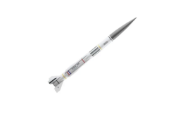
Acrotech 89012 hv arcas scale model rocket

About Acrotech
In 1982, Gary C. Rosenfield established AeroTech Consumer AerospaceTM (AeroTechTM) in Sacramento, California, to create, produce, and sell solid composite propellant hobby rocket motors. The “E6” and “F10” long-burning competition motors, as well as the “G30” “moonburning” motor, were the initial motors offered.
These motors were eventually distributed by Colorado Springs, Colorado-based Apogee Components. The merchants who sold the “rocket product only” were mail-order companies and usually operated at hobby rocket launch sites.
Gary and Daniel H. Meyer co-founded Industrial Solid PropulsionTM (ISPTM), Inc. in 1985 to design and produce solid composite propellant rocket motors for use in industrial, military, and aerospace settings.
Additionally, AeroTech and ISP moved their headquarters to Las Vegas, Nevada in 1985. Two years later, in 1987, they moved once more, this time to an industrial complex.
BEFORE YOU BEGIN
- Study the illustrations and sequence of assembly. The sequence of assembly is important. Review the parts list and become familiar with all parts before assembly. If any parts are missing or damaged, contact RCS at 1-435-865-7100 or email warranty@aerotech-rocketry.com.
- DO NOT MODIFY THE DESIGN OF THE ROCKET. Changes to the design of the rocket such as, but not limited to, reducing the fin size, shortening the body tube, or modifying the motor tube assembly can adversely affect the flight stability of the rocket.
- Only use AEROTECH® Composite Model Rocket Motors in this model rocket. See the recommended AEROTECH® motors chart on the box label.
Read and follow the Model Rocket Safety Code of the National Association of Rocketry (NAR) and comply with all federal, state, and local laws in all activities with model rockets.
PARTS:
- Motor adaptor tube (4-7/8″/124mm)(12421) 1
- Adaptor rings (1/2″/13mm) (14001) 2
- “E” spacer tube (2-1/8″/54mm) (14002) 1
- Thrust ring (7/16″/11mm) (14010) 1
- Thrust ring flange (1/16″/1.6mm) (14011) 1
- Motor tube (12″/30.5cm) (12912) 1
- Motor hook (19001) 1
- FIN-LOK™ rings-4 fin (19344) 2
- Centering rings (2-17/32″/64mm) (16629) 3
- Fins (11712) 4
- Cooling mesh (19011) 1
- Ejection gas baffle (19030) 1
- Screw eyes (19015) 2
- Fin can tube (4-1/8″/10.5cm) (12704) 1
- Shock cord (8’/2.4m) (17388) 1
- Slotted body tube (24″/61cm) (12623) 1
- Upper body tube (19″/48cm) (12619) 1
- Bulkhead (1/16″/1.6mm) (16609) 1
- Coupler tube (6″/15cm) (12606) 1
- Launch lugs (19035) 2
- Nose cone (11261) 1
- Adhesive decal sheet (18012) 1
- Parachute (30″/76cm diameter) (13030) 1
- “F” spacer tube (1″/25mm) (14003) 1
- Aluminum data plate (18912) 1
- Blueprint (19812) 1
- Instructions (19912) 1
ASSEMBLY INSTRUCTIONS
MOTOR ADAPTOR

- Lightly sand the motor adaptor tube and then slide an adaptor ring onto the tube until the end of the ring is flush with the end of the tube. This ring marks the front end of the adaptor tube. Slide the other adaptor ring onto the other end of the adaptor tube until the back edge of the ring is 3/4″ (19 mm) from the back end of the tube. Apply beads of cement where the rings meet the adaptor tube.
- Insert the “E” motor spacer tube into the motor adaptor tube and position it at the front end of the adaptor tube. DO NOT cement in place.

MOTOR TUBE ASSEMBLY

- Cement the thrust ring flange (1/16″/1.6 mm thick) to the thrust ring (7/16″/11 mm long). Set the thrust ring assembly aside to dry.
- Find the line drawn along the side of the motor tube. Using the Location Guide printed along the top edge of this instruction sheet, cut a 1/4″ (6 mm) long slot 4-5/8″ (117mm) from the back end of the motor tube and next to the line on the motor tube as shown.
- Using the Location Guide, make a mark along the motor tube line 2-15/16″ (75 mm) from the back end of the motor tube. This mark locates where the back edge of the front FIN-LOK™ ring will be. Make another mark 7/8″ (22 mm) from the back end of the motor tube. This mark is located where the front edge of the rearmost FIN-LOK™ ring will be.
- Insert the tab of the motor hook into the slot cut into the motor tube. Use a small dowel to apply several drops of cement around the inside of the motor tube just behind where the motor hook comes through the motor tube wall. Then, with the thrust ring flange facing the back, insert the thrust ring assembly into the motor tube. Use the motor adaptor to push the thrust ring assembly forward until it stops against the tab of the motor hook. Remove the motor adaptor.
FIN-LOK™ ASSEMBLY

- With their motor hook channels aligned with the motor hook, slide a FIN-LOK™ ring and then an AERO-FIBRE™ centering ring over the front end of the motor tube. Push on the centering ring until the back edge of the FIN-LOK™ ring is moved to the forwardmost mark made in Step 3 above. (NOTE: The rings are designed to be a tight fit on the motor tube. If the rings are difficult to slide onto the motor tube,s and the inside surface of the rings with sandpaper. If the FIN-LOK™ rings need to be turned after they are on the motor tube, use a small piece of cloth to provide a better grip.)
- Slide the other FIN-LOK™ ring and then a centering ring over the back end of the motor tube. Push on the centering ring until the front edge of the FIN-LOK™ ring is at the rear-most mark made in Step 3.
- Using the line on the motor tube as a guide, gently twist the back centering ring slightly until the fin locks of the back FIN-LOK™ ring are aligned with the fin locks of the front FIN-LOK™ ring.

- Test the proper positioning and alignment of the FINLOK™ rings by snapping the fins into the fin locks. If any fin does not snap into place, check to see that each FINLOK™ ring is the correct distance from the back end of the motor tube and that the fin has no plastic flashing left from production that may be preventing a proper fit. Remove any plastic flashing with a hobby knife or sandpaper. After making any adjustments, carefully remove the fins and the back centering ring. Check that the front centering ring is still positioned next to and touching the front FINLOK™ ring.
- Apply a bead of cement where the front centering ring meets the motor tube. Without getting cement into any of the flocks, apply cement only to the areas BETWEEN the flocks where the front FIN-LOK™ ring meets the front centering ring and the motor tube.
- Without getting cement into any of the fin locks, apply cement only to the areas BETWEEN the fin locks where only the front edge of the back FIN-LOK™ring meets the motor tube. DO NOT apply cement to the back edge of the back FIN-LOK™ ring. (NOTE: The unique AEROTECH® FIN-LOK™ fin mounting system carries and distributes aerodynamic and thrust loads throughout an integrated rocket structure in a manner found in large aerospace vehicles. Loads are primarily borne by structural members and not cement.)
- Apply a bead of cement around the motor hook forward of the front centering ring.
LABYRINTH™ ASSEMBLY

- Make four 1/4″ (6mm) long cuts, 90 degrees apart, in the front end of the motor tube.
- Stretch out the cooling mesh to about 6″ (15cm) in length. Insert the cooling mesh into the front end of the motor tube. (NOTE: Do not cement the mesh into the motor tube.)
- Apply a thin film of cement to the front two-thirds of the shoulder of the ejection gas baffle and insert the baffle shoulder into the front end of the motor tube.
- Apply beads of cement where the baffle meets the motor tube and into each of the cuts in the motor tube.
- Apply cement to the front surface of the baffle flange and place an AERO-FIBRE™ centering ring over the front end of the baffle so it rests upon the baffle flange.
- Screw a screw eye into the hole at the front end of the baffle. Securely tie an end of the shock cord to the screw eye with a square knot. (CAUTION: Do not put cement on the knot of the shock cord. Cement will weaken the shock cord.)
LOWER BODY AND FIN ASSEMBLY

- Using a hobby knife, carefully remove any body tube material that may still be attached to any pre-cut slots in the slotted body tube.
- Insert the loose end of the shock cord and then the motor tube assembly into the back of the rocket body tube as shown. Position the motor tube assembly so that the fin locks are located under and visible through the body tube’s pre-cut fin slots.
- Apply cement along the back 4-1/8″ (10.5 cm) of the fin root of a fin (area of the fin next to the outside surface of the body tube). (NOTE: The forward 1-5/8″ (1.6 cm) of the fin root stands away from the surface of the body tube.) Carefully insert the fin through a slot in the body tube and push the fin in until it makes contact with the FIN-LOK™ ring. Snap the forward part of the fin tab into the forward FIN-LOK™ ring. Then snap the back part of the fin tab into the back FIN-LOK™ ring. Gently wiggle the fin from side to side to make sure the body tube “pops” back into position against the fin root surface. Repeat this process for the other three fins.
4. Through the back end of the body tube, apply cement where the fin tabs meet the motor tube, fin locks, front centering ring, and body tube. Through the front end of the body tube, apply cement where the baffle assembly centering ring meets the inside surface of the body tube.
5. Lightly sand the surface of the body tube around the launch lug slots. Apply cement to the base of a launch lug. With the sloping portion of the launch lug toward the front of the body tube, insert the tab on the bottom of the lug into one of the pre-cut launch lug slots in the body tube. Repeat this process for the other launch lug.
FIN CAN ASSEMBLY
- Cut out and wrap the Fin Can Line Guide around the fin Hole can tube. Make sure the edges of the guide are flush with the ends of the fin can tube. Mark the tube at the ends of the dotted lines on the guide. Then use a pin to mark the corners of the rectangular hole for the back launch lug. (NOTE: Do not throw away the decal instructions.)
- Using the marks as a guide, draw five lines along the length of the fin can tube. Cut the tube into five segments along these lines. Discard the narrow segment.
- Locate the fin can segment with the four pin holes made in Step 1. Using these holes as a guide draw a rectangle. Cut out the rectangle using a hobby knife. (NOTE: This rectangular hole should fit over the back launch lug. Its back edge should be 1-1/8″ (28.6 mm) from the back edge of the fin can segment.)
- The cement fin can be segmented with the rectangular hole between the fins where the back launch lug is located. The back edge of the segment should be flush with the back edge of the lower body and fin assembly.

- Cement the other three fins can segments between the fins as shown.
- Paint the rocket body and fins 1,2 and 3 white. Paint in 4 a shade of red that matches the red of the decal sheet.
UPPER BODY ASSEMBLY

- Paint the back 12-7/16″ (31.6 cm) of the upper body tube white. Paint the rest of the tube and the nose cone a shade of red that matches the red of the decal sheet.
- Screw the other screw eye into the hole in the bulkhead (1/16″/1.6 mm thick). Apply a bead of cement where the screw eye meets the bulkhead.
- Pass the free end of the shock cord through the coupler tube (6″/15 cm long) and securely tie it to the screw eye attached to the bulkhead with a square knot. (CAUTION: Do not put cement on the knot of the shock cord. Cement will weaken the shock cord.)
- Cement the bulkhead to the end of the coupler tube.
- Make a pencil mark 3″ (76 mm) from the end of the coupler tube. Lightly sand the surface of the tube between the mark and the bulkhead. Use a small dowel to apply a bead of cement around the inside of the upper body tube about 1″ (25mm) from the end of the tube. Then slide the coupler tube into the payload bay tube up to the pencil mark on the coupler tube.
- Cement the nose cone into the forward end of the upper body tube.
FINAL ASSEMBLY AND FINISHING

- Slide the remaining centering ring over the back of the motor tube and motor hook and push it against the back FIN-LOK™ ring. Apply a bead of cement where the centering ring meets the body tube.
- Carefully cut out the self-adhesive decals and apply them to the rocket body. See “Decal Instructions” for helpful hints. Use the picture on page 1 as a guide to proper positioning.
- Fasten the fabric parachute to the shock cord at a point about one (1) foot away from the payload bay in the following manner. Stretch out the shroud lines of the parachute so that the lines form three (3) loops on top of each other. Lay the shock cord across all the shroud lines. pass the canopy of the parachute over the shock cord and through the three (3) loops made by the shroud lines and pull tight. Pack the parachute and insert the upper body assembly into the lower body assembly.
- Carefully peel off the backing of the aluminum data plate. Starting at its top edge, apply the data plate to the upper body so that its right-hand edge is 10-1/4″ (26.0 cm) from the forward edge of the upper body tube. (CAUTION: The adhesive on the aluminum plate is strong. The plate cannot be repositioned once it is put in place without damaging the plate.)
OPERATION INSTRUCTIONS
- RECOMMENDED MOTORS: Only use AEROTECH composite model rocket motors when flying your AEROTECH rocket. See the enclosed chart for recommended motors and projected altitudes.
- RECOVERY SYSTEM PREPARATION: Roll the parachute and shroud lines, starting from the canopy peak, into a loose cylinder that will easily slide into the lower body assembly body tube.
- MOTOR PREPARATION: The motors recommended for your AEROTECH rocket vary in physical size as well as performance. Your rocket comes with a changeable motor adaptor and spacer tubes that permit the rocket to use each of the recommended motors without permanent modification to the rocket.
- PRE-LAUNCH CHECKOUT: Before EVERY flight, perform a complete pre-launch checkout of your rocket;
- Check that all fins and launch lugs are mounted securely and not damaged.
- Examine the body tube, nose cone, and payload bay to make sure they are free of damage.
- Check that the shock cord is securely mounted to the ejection gas baffle and nose cone (or payload bay bulkhead).
- Check that the parachute is securely tied to the shock cord.
- Check that the shock cord and parachute are free of any damage.
- LAUNCH PAD: Your AEROTECH rocket must be flown from a launch pad with a 1/4″(6.4mm) diameter metal launch rod at least 36″(0.9m) long (as measured from the top of the blast deflector), such as the AEROTECH MANTIS™ model rocket launch pad.
- MOTOR IGNITION: Only launch your rocket using a remotely controlled and electrically operated launch controller such as the AEROTECH® INTERLOCK™ model rocket launch controller. Keep yourself and all other people at least 30 feet (10 meters) away from the rocket during launch.
- LAUNCH AREA: Launch the rocket in a cleared outdoor area free of tall trees, power lines, and buildings. The side dimensions of the cleared area should be at least one-half of the projected altitude.
- FLIGHT PROFILE: When the launch button of the electrical launch controller is pressed, an electrical current causes the AEROTECH COPPERHEAD™ single lead igniter to ignite the composite propellant of the AEROTECH rocket motor. The motor quickly builds up thrust and powers your AEROTECH rocket into the air.
- TRANSPORT AND STORAGE: To avoid damage to your AEROTECH rocket during transport, pack it in a box surrounded by soft packing. Store your rocket at room temperature.
DECAL INSTRUCTIONS
Here are some helpful hints to make decal application easy and accurate.
- Handle the decal sheet carefully to avoid damage. Do not crease the decal sheet.
- Use a pair of sharp scissors or a hobby knife to cut out the decals.
- Cutting out names as a block will make name decals easier to apply.
- Make smooth cuts. Small knicks can cause a decal to tear when it is being peeled off the backing sheet.
- Before starting to peel decals off their backings, fill a soup bowl with warm water and put one or two drops of dishwashing detergent into the water.
- Carefully peel a decal off its backing, dip it into the detergent solution, and apply the decal to the rocket. Use the photograph on the cover of the box as a guide to proper positioning. The detergent solution prevents the adhesive on the decal from “grabbing” the rocket surface too quickly and allows accurate positioning of the decal.
- Gently press any air bubbles out from under the decal and then dab the decal dry.
- Apply the rest of the decals in the same manner.
HV ARCAS Kit
Your kit now includes a new improved screw-on motor retainer. Please follow these instructions.
STEP 1.
The following parts are NO LONGER included in this kit:
- Thrust Ring (14010),
- Thrust Ring Flange (14011)
- Motor Hook (19001)
- Motor Adapter Tube (12421)
- Adaptor Rings (2) (14001)
STEP 2.
Disregard the following Steps in the instructions:
- MOTOR ADAPTOR – Disregard Step 1 and Step 2.
- MOTOR TUBE ASSEMBLY – Disregard Step 1, Step 2, Step 4.

Use the LOCATION GUIDE above to make pencil marks along the motor tube line for the location of the FIN-LOK rings per STEP 3. The new marks will move the motor tube rearward so that it is flush with the end of the body tube. Follow Step 1 of FIN-LOK ASSEMBLY using new location marks as above.
STEP 3.
Follow the instructions included with your 29mm motor retainer to install it on the end of the motor tube AFTER completing the installation of the Rear Centering Ring in STEP 1 of FINAL ASSEMBLY AND FINISHING.
NOTICE:
As we cannot control the storage and use of our products, once sold we cannot assume any responsibility for product storage, transportation, or usage. RCS shall not be held responsible for any personal injury or property damage resulting from the handling, storage, or use of our product. The buyer assumes all risks and liabilities therefrom and accepts and uses AeroTech/RCS products under these conditions.
AeroTech Division
RCS Rocket Motor Components, Inc. Cedar City, UT 84720
www.aerotech-rocketry.com
For More Manuals by Acrotech, Visit LatestManuals