Honeywell PL-1000 Fire Alarm Control Panel

Loop Module PL-LIB-01 – Honeywell
The PL-LIB-01 kit includes:
- 8 x plastic spacer
- 1 x 20 pole ribbon cable
Panel Installation

- STEP 1
Hold the panel backbox horizontally (align using a spirit level) on the mounting surface and mark the 3 mounting holes.
- STEP 2
Drill the wall on the three fixing points and utilize the accessories included with the panel (3,5 x 25 mm) to secure the panel on the wall. - STEP 3
Put the screw in the hole, align the screw on the cover with the keyhole on the back, then insert the screws in the holes to complete the panel installation.
Cable Entries

- Upper 15 cable glands Ø 21 mm
- Back 8 cable glands Ø 21 mm
- Cable entry easy to break
Mains Connections

- Remove the outer sheath of cable 1 to provide enough slack, approx. 80 mm, for the cables to help during connection.
- From a loop with each conductor before presenting it on its terminal where it is to be connected. Guide the conductor L and N 2 in such a way that there is a separation from the safety ground.
- Connect the L and N conductors directly to terminal block 3 (left and right terminal respectively). The safety ground conductor must be connected to the panel terminal.
Battery Connections

- Install the batteries inside the back box on the bottom 5.
- The batteries shall be positioned in such a way their terminal is close enough to allow the connection of the short connection cable 7.
- Connect the batteries using the supplied cable:
- Connect the red and black (+ / -) cable plug to the main board 4.
- Connect batteries with the short cable 7.
Main Board Connections

Sounder circuit
End of line diode cathode marker on the positive terminal.
- 24 V +
- 24 V –
- SND1 +
- SND1 –
- SND2 +
- SND2 –
- Loop 1 A+
- Loop 1 A –
- Loop 1 B+
- Loop 1 B11 Digital IN 1+
- Remote Silence Sounders
- Digital IN 2+ Remote Reset
- GND
- Fault Relay Common
- Fault Relay Normally Closed
- Fault Relay Normally Open
- Alarm Relay Common
- Alarm Relay Normally Closed
- Alarm Relay Normally Open
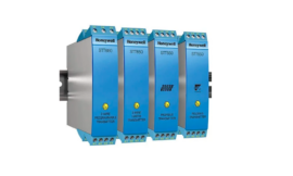
Expansion Loop Card Connection

Installation
- Put the plastic spacers 1 into the predisposed hole 1 on the back box
- Connect the ribbon cable 2 on the Loop Module PL-LB-01
- Install the Loop Module onto the plastic spacer 1
- Connect the ribbon cable 2 to the main board
Panels Display Controls, Buttons and Password


Quick Programming Procedure with Default General Alarm Functionality
- On the touchscreen display press the arrow on the right and then press the gear icon at the top right:
- Insert password level 2, press enter then press on the program icon, insert password level 3 and press enter to confirm.
- Select Panel Configuration to change the language using the arrow-down icon. Once completed, press the left arrow to come back to the previous screen.
- Select Autoprog, press the Lens icon to search for devices, and at the end of the process save devices detected with a check mark. Press the left arrow to come back to the previous screen. Please note: Default zone assigning: Sensors = Z1, MCP = Z2, Input modules = Z3, Output modules = Z4.
- Select Description to change both Zone and Point labels. This example refers to Zones: Press the Zone icon, type the label using the virtual keyboard,d, and confirm with enter. The same applies to Points.
- Come back to the Configuration menu using the left arrow and set Date and Time. The example shares how to change the Date: select the Date icon, scroll up and down the day, month, and year values then confirm with a check mark. To change Time, follow the same process.
Honeywell House
Skimped Hill Lane BRACKNELL Berkshire, RG12 1EB UK
For More Manuals by Honeywell, Visit Latest Manuals
FAQs About Honeywell PL-1000 Fire Alarm Control Panel
What location is ideal for the fire alarm control panel?
FACPs are frequently positioned near the front entry for this reason. Larger structures may have them in an enclosed emergency control room; in that case, annunciators must be installed so that anyone within may hear the alarm signal from the panel.
How are alarm control panels operated?
When sensors malfunction, alarm systems communicate their findings to a central monitoring station. The alarm control panel is the focal point of an alarm system. With the panel, all system sensors and other devices are in communication. A communicator is required by the panel to send out signals.
Do I need a fire alarm panel?
In legal terms, not always. However, we always advise having a heat or smoke alarm in each room where a fire can occur. Your space is open-plan, one-story, compact, and uncomplicated.
Is a fire control panel necessary?
If your business building has a commercial fire system, you will require a fire panel. By doing this, you may maintain the insurance compliance and safety of your commercial property while simultaneously employing sensible fire safety procedures to safeguard your personnel, property, and assets.
What is the fire alarm control panel’s minimum height requirement?
Are you prepared to do it? The minimum and maximum installation heights for fire alarm control units have been modified. It may seem strange that NFPA 72 does not currently have these criteria, but it does. It is now necessary to put control units 1.5–5.5 feet above the finished floor.
Does battery power power alarm control panels?
Common Configurations for Alarm Systems Electric power is typically used to operate control panels, which govern the system. They might, nevertheless, feature a backup battery that can provide more power when required. Battery-operated hardwired smoke detectors are common. Batteries are frequently the only power source for motion detectors.
What alerts the fire panel with an alarm signal?
All circuits and devices that provide a signal to a fire alarm control unit (FACU) are included in the components. Examples of these are pressure switches, water flow switches, heat, smoke, and carbon monoxide detectors. What alerts the fire panel with an alarm signal?
How is the Honeywell fire alarm panel silenced?
Follow these steps to recognize the fault state and turn off the panel-sounding device: Toggle the “TROUBLE ACKNOWLEDGE” switch on the SCU or display. Additionally, holding down this switch will keep the display stable. NOTE: IT IS REQUIRED TO ACKNOWLEDGE MULTIPLE TROUBLE INDICATIONS INDIVIDUALLY.
How can the Honeywell fire panel be reset?
For approximately thirty seconds, press and hold the action button located in the center of the top of the base station. The Base Station will inquire as to your level of confidence before executing a device factory reset.
When should a fire alarm panel be replaced?
An upgrade may be the best course of action if your system is more than ten years old and is becoming too costly to maintain. However, yearly repairs and similar maintenance will guarantee that your current system will continue to function, ensuring the safety of every employee in the building in the event of a fire.
How often should fire alarm panels be tested?
Ideally, once a week. This will allow for routine visual inspections and basic tests to be
How often is it appropriate to inspect a fire alarm panel?
every week How frequently ought fire alarms should be checked? Article 17 of the RRO covers the legal requirement to conduct weekly fire alarm tests in addition to the minimum requirement of six monthly inspections.
What is a fire alarm panel’s voltage?
24 volts These days, all fire alarm systems run on 24 volts. The standby batteries on medium- and larger-sized fire alarm systems sometimes don’t fit inside the control panel.
How often is it appropriate to inspect a fire alarm panel?
every week How frequently ought fire alarms should be checked? Article 17 of the RRO covers the legal requirement to conduct weekly fire alarm tests in addition to the minimum requirement of six monthly inspections.
Is it necessary to have a smoke detector atop the fire alarm control panel?
A smoke detector must be installed above the component if it is UL-classified as a fire alarm control unit.