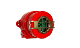
Honeywell RMA805 Enraf FlexLine Remote Indicator

Installation and Startup – Honeywell
Installation Site Evaluation
Evaluate the site selected for the RMA805 Enraf FlexLine Remote Indicator installation concerning the process system design specifications and Honeywell’s published performance characteristics for your particular model. Some parameters that you may want to include in your site evaluation are:
- Environmental Conditions:
- Ambient Temperature
- Relative Humidity
- Potential Noise Sources:
- Radio Frequency Interference (RFI)
- Electromagnetic Interference (EMI)
- Vibration Sources
- Motorized System Devices (e.g., pumps)
Display Installation Precautions
Temperature extremes can affect display quality. The display can go blank if the temperature is below -20°C or above +70°C; however, this is only a temporary condition. The display will again be readable when temperatures return to within operable limits.
Mounting Remote Indicator Summary
Remote Indicator models can be attached to a two-inch (50-millimeter) vertical or horizontal pipe using Honeywell’s optional pipe mounting bracket. Honeywell’s optional wall mounting bracket is also shown below.
Figure 1 shows typical bracket-mounted installations.


Mounting Dimensions
Refer to Honeywell drawing number 50094836 for detailed electronic housing dimensions. Refer to Honeywell drawing numbers 50095917 for detailed pipe mounting dimensions and 50095918 for detailed wall mounting dimensions.
Abbreviated overall dimensions are also shown on the Specification Sheets for the Remote Indicator models. This section assumes that the mounting dimensions have already been taken into account and the mounting area can accommodate the Remote Indicator.
Bracket Mounting
If you are using an optional bracket, start with Step 1.
- Align the two mounting holes in the Remote Indicator with the two slots in the mounting bracket and assemble the (2) M8 hex cap screws, (2) lock washers, and (2) flat washers provided. Rotate the Remote Indicator assembly to the desired position and torque the M8 hex cap screws to 27,0 Nm/20,0 Lb-ft maximum.
Pipe Mount Option: Refer to Figure 2 - Position the bracket on a 2-inch (50.8 mm) horizontal or vertical pipe, and install a “U” bolt around the pipe and through the holes in the bracket. Secure the bracket with the nuts, flat washers, and lock washers provided.
- Wall Mount Option: Position the bracket on the mounting surface at the desired location and secure the bracket to the mounting surface using the appropriate hardware (Wall mounting hardware requirements to be determined and supplied by the end-user)

Wiring the RMA805 Enraf FlexLine Remote Indicator
Overview
The Remote Indicator must be connected to the local HART-compatible bus of the Enraf Smartradar FlexLine or the Enraf SmartServo 954. The Remote Indicator has 3 terminals. The following table provides the connection details:
 The screw terminals are suitable for wirings up to 16AWG (1.3 mm2 ) Shielded, twisted pair cables such as Belden 9318 or equivalent must be used for all wiring. The cable shield must be connected at only one end of the cable. Connect it to the FlexLine Gauge side and leave the shield insulated at the Remote Indicator side.
Note: If the solid core wire is used strip insulation 1/4 in (6 mm). Once inserted under the square washer the stripped portion should be contained under the square washer. If multi-stranded wire is used, a ferrule is to be used and the stripped wire should be in the insulated portion of the ferrule. The ferrule can also be used on the solid core wire.

Electrical Wiring
The Remote Indicator shall be connected to the Loop + and Loop – terminals of the FlexLine Gauge. Typically, these are terminals 24 and 25. See the installation manual of the FlexLine Gauge for more information. It is possible that other devices such as a VITO temperature convertor and a pressure transmitter must be connected to the same loop.
All devices must be wired in parallel. Ensure all devices are set to 4 mA digital multi-drop mode before connecting to the FlexLine Gauge. See Figure 4 for a connection diagram.
ATTENTION
Wiring must comply with local codes, regulations, and ordinances. Grounding may be required to meet various approval body certifications, for example,e CE conformity. Refer to Appendix A of this document for details.

Wiring Procedure
- See Figure 3, for parts locations. Loosen the end cap lock using a 1.5 mm Allen wrench.
- Remove the end cap cover from the terminal block end of the electronics housing.
- Feed loop power leads through one end of the conduit entrances on either side of the electronics housing. The Remote Indicator accepts up to 16 AWG wires.
- Plug the unused conduit entrance with a conduit plug appropriate for the environment.
- Torque terminal screws to 0.6 Nm (5.3 lb. in) to 0.8 Nm (7.0 lb. in).
- Connect the Loop Power wiring shield to earth ground only at the power supply side.
- Replace the end cap and secure it in place being careful not to damage the wires.
Explosion-Proof Conduit Seal
WARNING
When installed as explosion-proof in a Division 1 Hazardous Location, keep covers tight while the Remote Indicator is energized. Disconnect power to the Remote Indicator in the nonhazardous area before removing end caps for service.
Jumper Settings
On the Remote Indicator, there is a failsafe jumper and a write-protect jumper behind the display on the Communication Module. The top jumper is the failsafe jumper. It is highly recommended to put the failsafe jumper to DOWN (Downscale). The bottom jumper sets the right to protect.


Configuration Guide
The Remote Indicator 3-button interface provides user interface and operation capability without opening the Remote Indicator. The user must press the button to call up the Main Menu. To exit the Main Menu and return to the PV display screen, select.
Use the button to scroll through the list of menu items. Press the button to select an item for data entry or activation. When an item is selected for data entry or activation, the cursor is positioned over the leftmost digit to allow editing of the value. No action is taken against a menu item until the button is pressed.


Appendix A. PRODUCT CERTIFICATIONS
A1. Hazardous Locations Certifications


Operating Parameters:
- Voltage= 12 to 42 V
- Current= 25 mA
Intrinsically Safe Entity Parameters
For details see Control Drawing, 50089981.
A2 Marking ATEX Directive
General
The following information is provided as part of the labeling of the Remote Indicator: Name and Address of the manufacturer The serial number of the Remote Indicator is located on the Meter Body data plate.
The first two digits of the serial number identify the year (12) and the second two digits identify the week of the year (23); for example, 1223xxxxxxxx indicates that the product was manufactured in 2012, in the 23rd week.
Apparatus Marked with Multiple Types of Protection
The user must determine the type of protection required for the installation of the equipment. The user shall then check the box [ ] adjacent to the type of protection used on the equipment certification nameplate. Once a type of protection has been checked on the nameplate, the equipment shall not then be reinstalled using any of the other certification types.
A.3 Conditions of Use” for Ex Equipment”, Hazardous Location Equipment or “Schedule of Limitations”:
- Consult the manufacturer for dimensional information on the flameproof joints for repair.
- The painted surface of the RMA 800 series may store electrostatic charge and become a source of ignition in applications with low relative humidity of less than approximately 30% relative humidity where the painted surface is relatively free of surface contamination such as dirt, dust, or oil. Cleaning of the painted surface should only be done with a damp cloth.
- The ambient temperature range and applicable temperature class of the equipment are as follows:
RMA805 series: T4 for -50˚C < Ta < 70˚C - The RMA800 series enclosure contains aluminum and is considered to present a potential risk of ignition by impact or friction. Care must be considered during installation and use to prevent impact or friction to avoid impact.
- If a charge-generating mechanism is present, the exposed metallic part on the enclosure is capable of storing a level of electrostatic charge that could become incendive for IIC gases. Therefore, the user/installer shall implement precautions to prevent the buildup of electrostatic charge, e.g. earthing the metallic part. This is particularly important if the equipment is installed in a zone 0 location.
- On installation, the RMA800 series shall be provided with supply transient protection external to the apparatus such that the voltage at the supply terminals of the RMA800 series does not exceed 140% of the voltage rating of the equipment. However, when an RMA805 is connected to a SmartRadar FlexLine or a SmartServo 954 the supply transient protection is included in the SmartRadar FlexLine or SmartServo 954.
WARRANTY
Honeywell warrants goods of its manufacture as being free of defective materials and faulty workmanship. Contact your local sales office for warranty information. If warranted goods are returned to Honeywell during the period of coverage, Honeywell will repair or replace without charge those items it finds defective.
The foregoing is Buyer’s sole remedy and is instead of all other warranties, expressed or implied, including those of merchantability and fitness for a particular purpose. Specifications may change without notice. The information we supply is believed to be accurate and reliable as of this printing. However, we assume no responsibility for its use.
While we provide application assistance personally, through our literature and the Honeywell website, it is up to the customer to determine the suitability of the product in the application.
Sales and Service
For application assistance, current specifications, pricing, or the name of the nearest Authorized Distributor, contact one of the offices below.
ASIA PACIFIC
Honeywell Pte Ltd. 17 Changi Business Park Central 1 Singapore 486073
Phone: +65 6355 2828
Email: (Sales)
Email:
enraf-sg@honeywell.com
or (TAC)
hfs-tac-support@honeywell.com
Web
Knowledge Base Search
engine http://bit.ly/2N5Vldi
EMEA
Honeywell Enraf Delftechpark 39 2628 XJ Delft The Netherlands
Phone: +31 (0)15 2701 100
Email: (Sales)
Email:
enraf-nl@honeywell.com
or (TAC)
hfs-tac-support@honeywell.com
Web
Knowledge Base Search
engine http://bit.ly/2N5Vldi
Americas
Honeywell Enraf Americas, Inc. 1250 West Sam Houston Pkwy S. Houston, TX 77042,
USA
Phone: +1 (480) 293-2042
Email: (Sales)
Email:
enraf-us@honeywell.com
or (TAC)
hfs-tac-support@honeywell.com
Web
Knowledge Base Search
engine http://bit.ly/2N5Vldi
Documentation
To access complete documentation, including language variants, scan the QR code below using your smartphone/device or QR code scanner. Go to the APP store for your free Smartphone QR scanner Or you can follow the URL to access the online Tank Storage Documentation. The Documentation page will contain direct links to open the product documentation.
URL QR Code https://www.hwll.co/TankStorageDocs
For more information
To learn more about SmartLine Devices, visit process.honeywell.com
Or contact your Honeywell Account Manager
Process Solutions Honeywell
1250 W Sam Houston Pkwy S Houston, TX 77042 Honeywell Control Systems Ltd Honeywell House, Skimped Hill Lane Bracknell, England, RG12 1EB Shanghai City Centre, 100 Jungi Road Shanghai, China 20061
process.honeywell.com
FAQs About Honeywell RMA805 Enraf FlexLine Remote Indicator
What is the Honeywell RMA805 Enraf FlexLine Remote Indicator?
The Honeywell RMA805 Enraf FlexLine Remote Indicator is a device used for remote indication of process variables in industrial applications. It is part of the Enraf FlexLine product line, designed for accurate and reliable measurement and monitoring of various process parameters.
What are the key features of the RMA805?
The RMA805 features a large, easy-to-read display, configurable engineering units, and various communication options for seamless integration into industrial control systems. It is designed for durability and performance in harsh industrial environments.
What parameters can the RMA805 measure?
The RMA805 is capable of measuring various process variables such as pressure, temperature, level, and flow, depending on the configuration and application requirements. It offers flexibility to adapt to different measurement needs.
How does the RMA805 communicate with other devices or systems?
The RMA805 supports communication protocols such as Modbus RTU, Modbus TCP/IP, HART, and Profibus DP, allowing seamless integration with distributed control systems (DCS), programmable logic controllers (PLC), and other industrial automation equipment.
Is the RMA805 suitable for hazardous areas?
Yes, the RMA805 is available in intrinsically safe (IS) and explosion-proof (Ex) versions, making it suitable for installation in hazardous areas where flammable gases, vapors, or dust may be present.
Can the RMA805 be easily configured and calibrated?
Yes, the RMA805 features intuitive configuration menus and onboard calibration procedures, enabling easy setup and maintenance by plant operators or maintenance personnel.
What are the typical applications for the RMA805?
The RMA805 is commonly used in various industries such as oil and gas, petrochemical, chemical processing, power generation, water and wastewater treatment, and pharmaceuticals, for monitoring and control of critical process parameters.
Does Honeywell offer technical support or documentation for the RMA805?
Yes, Honeywell provides comprehensive technical support, documentation, and training resources for the RMA805, including user manuals, datasheets, application notes, and online support portals.
Can the RMA805 Enraf FlexLine Remote Indicator be used in hazardous areas?
Yes, Honeywell offers models of the RMA805 that are suitable for use in hazardous areas, and certified to meet relevant safety standards such as ATEX and IECEx.
Is the RMA805 Enraf FlexLine Remote Indicator configurable?
Yes, the RMA805 is configurable via its intuitive interface or through software tools provided by Honeywell. Users can adjust settings, calibrate sensors, and customize display parameters to suit specific application requirements.
For More Manuals by Honeywell, Visit Latest Manuals