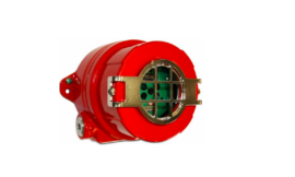
Honeywell W4267_I DHS Mini Detector

About Honeywell
The inconvenience of having to manually adjust the furnace arose with the introduction of home furnace heating. The company that became Honeywell was founded by inventor Albert Butz, who received patents for the furnace regulator and alarm.
The resulting “damper flapper” was the first of several Honeywell inventions and an ancestor of the modern thermostat. The furnace damper’s remote control setting established the standard for automation-based convenience.
After purchasing Butz’s business and patents, the Consolidated Temperature Controlling Co. changed its name to Electric Heat Regulator Co. by 1893.
W. R. Sweatt acquired the business in 1898, and by 1916, he had renamed it the Minneapolis Heat Regulator Company, increased its product offering, and obtained a patent for the first electric motor that Underwriters Laboratories had authorized.
Electrical Connections – Honeywell

Mounting Details
The MSM2000 Control Module is designed to be mounted within the luminaire on fixing centers of 135mm. Connections to the control module as shown above should be made using solid strand wire (0.5-1.5 mm).
The interconnect cable between the detector head and control module should be routed away from another luminaire internal wiring and away from the lamp end-caps.
The recommended position for the detector is in the middle of the luminaire. Where this is not possible and the detector is fitted near on end of the lamps, please ensure that the detector is at the ‘cold’ end of the lamps.
The DHW/S Mini Detector Head should be mounted such that only the raised front section of the bezel protrudes through the cut-out in the louver or infill panel, constructed by the dimensions above.
Installation Guidelines
- The Mini Detector Head must be mounted within the luminaire. Do not mount remotely.
- The connecting cable must not be extended.
- Artificial light illuminating the Mini Detector Head must only be reflected from the room – i.e. there must be no direct illumination.
- To receive satisfactory light-level regulating operation, a detector must observe a substantially greater proportion of artificial light from the luminaire(s) under its control than from neighboring luminaires not under its control. This is particularly important when planning the installed layout of linear luminaires that have an integral detector positioned at one end.
Commissioning
Detectors are supplied factory pre-set which ensures the lighting will switch on automatically as soon as power is applied. Final commissioning of the detectors requires the use of an infrared Programmer. The QuickSet Pro gives access to the full range of parameters and options but limited programming functions can also be carried out using an HP18.
Commissioning Detectors using the QuickSet Pro Programmer
The Programmer must be held perpendicular between 0.5m and 2m from the sensor.
- Switch on by pressing any button (and unlock with the top left rectangular button).
- Point the programmer at the detector and press the DOWNLOAD button. The programmer will confirm the product’s identity and call up the correct menu of parameters and their current settings.
- Use a combination of UP, DOWN, FORWARD, and BACK buttons to navigate the parameter menu, selecting options for each shown.
- When options for all parameters have been selected, point the programmer at the detector and press the UPLOAD button. The luminaire(s) will switch off briefly during the programming process.
- After a short period of inactivity (default 5 minutes), the programmer hibernates retaining the most recent settings.
OneSwitch Dimming
OneSwitch dimming affords local control to the end-user whereby a simple, momentary, push-to-make wall switch can be used to raise or lower the lighting level or toggle the output ON/OFF.
A press of less than 1 second will toggle the output status while a longer press will raise or lower the output. Each time the switch is pressed, the direction of dimming reverses.
If the switch has not been pressed for 5 seconds, the direction will be up (brighter) – unless the output is already above 90% (dc 8V) in which case the direction is down.
To Test with a Hand-held Controller
Once the LightSpot Luminaire Controllers have been installed within the luminaires, a Hand-held Controller or Programmer (HC5A or HP18) may be used to dim and brighten luminaires and to switch them ON and OFF.
Technical Data
- MAXIMUM RECOMMENDED MOUNTING HEIGHT: 3.0m
- RANGE: Cone-shaped detection pattern, diameter (at floor level) = 2.4 x mounting height

- OPERATING VOLTAGE: 230V 50Hz (UK & Europe) ta = 0 – 50°C
- CAPACITY: Max 4 x DSI or DALI ballasts
- INTERCONNECT CABLE TEMPERATURE RATING: 60°C
- COLOUR: White (RAL9010) or silver bezel (DHW = White, DHS = Silver)
- MATERIAL: UV stabilized polycarbonate (DHW/DHS) Flame retardant PC/ABS (MSM2000D/DALI)
- IP RATING: 20
- DIMENSIONS: 32 (1) x 21 (w) x 18.6 (h) mm (DHW/DHS) 147 (1) x 30 (w) x 21 (h) mm (MSM2000D/DALI)
- WEIGHT: 32g incl. 0.8m cable (DHW/DHS) 48g (MSM2000D/DALI)
ImportantAdditional Notes
- A means for disconnection must be incorporated in the fixed wiring by the current wiring regulations.
- Although nominally 12V, the dimming output is not SELV and therefore should be treated with the same respect as mains about wiring practice. The OV line of the dimming output is almost at Neutral potential.
- The dimming control output should be connected only to the control input of the ballasts- never to other detectors.
- This equipment should be used to control only those ballasts powered from the same phase as the detector.
- Because the photocell is on the ceiling looking down, it is not possible for measurements made with a lux meter on the working plane to remain constant when daylight illuminates the ceiling and the working plane to a differing extent. Therefore, products of this type should be regarded as capable of maintaining an APPROXIMATE light level only.
- This equipment switches lights no more frequently than would a responsible human occupant. However, manufacturers of some particular lighting types (e.g. ‘2D’ luminaires) may specify a maximum number of switching cycles to achieve a predicted lamp life. Please check with the manufacturer of the luminaires to ensure that they are compatible with automatic controls in this respect.
- Some devices in this product range feature a silvered surface finish; this is intended for decorative purposes only Care should be taken to avoid accidental separation of the silvered coating from the product. If the unit is built into a luminaire that is subsequently wrapped in film having adhesive properties, it is recommended that a layer of suitable packaging material be used to protect the silvered area.
Honeywell Ex-Or
St. Marks Court, North Street, Horsham, West Sussex, RH12 1BW, UK.
Tel: +44 (0)1942 719229
Email: ex-ortechnicalsales@honeywell.com
www.ex-or.com
FAQs About Honeywell W4267_I DHS Mini Detector
What is the Honeywell W4267_I DHS Mini Detector?
The Honeywell W4267_I DHS Mini Detector is a motion sensor designed for use in security systems. It detects movement within its coverage area and triggers an alarm or other programmed response.
What does DHS stand for in the product name?
DHS stands for Dual Technology with Anti-Masking and Anti-occlusion.
What type of technology does the W4267_I DHS Mini Detector use?
The W4267_I DHS Mini Detector utilizes both passive infrared (PIR) and microwave technologies for enhanced detection accuracy and reliability.
What are anti-masking and anti-occlusion features?
Anti-masking and anti-occlusion features help prevent the detector from being intentionally covered or tampered with. This ensures that the sensor remains functional and effective in detecting motion.
What is the coverage area of the W4267_I DHS Mini Detector?
The coverage area varies depending on the installation height and mounting angle but typically ranges from several meters to tens of meters.
Is the W4267_I DHS Mini Detector suitable for indoor or outdoor use?
The W4267_I DHS Mini Detector is primarily designed for indoor use. However, it may be suitable for certain outdoor applications depending on environmental conditions and installation requirements.
How is the W4267_I DHS Mini Detector powered?
The detector is typically powered by low-voltage DC power from a security system control panel or a separate power supply.
Can the W4267_I DHS Mini Detector be integrated with other security systems?
Yes, the detector is designed to be compatible with a wide range of security systems and can be integrated seamlessly into existing installations.
Does the W4267_I DHS Mini Detector provide any tamper detection features?
Yes, the detector may include tamper detection features to alert the security system if it is tampered with or removed from its mounting location.
Is professional installation required for the W4267_I DHS Mini Detector?
While it is possible for technically savvy individuals to install the detector themselves, professional installation is recommended to ensure proper placement and functionality.
For More Manuals by Honeywell, Visit Latest Manuals
- Honeywell TurboForce Heater Fan User Guide
- Honeywell HZ-960 Series Infrared Heater User Guide
- Honeywell Remote Building Manager Express User Guide
- Honeywell TH6320U2008 Programmable Thermostat User Manual
- Honeywell FS20X Fixed Flame Detector User Guide
|
Honeywell W4267_I DHS Mini Detector Installation Guide [pdf] |